Supplementary Paper: Field Measurement of Grooves - Pre-2010 Rules
B
Supplementary Paper: Field Measurement of Grooves - Pre-2010 Rules
1.1
Guidance on how to Measure Grooves on Club Faces for Conformance to Pre-2010 Rules in the Field
1.1a
Introduction
The following pages give guidance on how to measure grooves on club faces for width and separation, using the “Ink and Scratch” method, and depth. They concentrate solely on the Rules which apply to the grooves on iron and wood clubs manufactured prior to 1 January 2010, but, if necessary, the same procedures and equipment can be used to measure grooves on a putter face (see Rule 5f of the Equipment Rules).For those Officials who have not carried out these measurements before, we recommend setting aside time, a day or more prior to the tournament, for groove checking if required, rather than doing it on the first day. It only takes a few minutes to measure the grooves on a club, but it is important not to be rushed. We also recommend practice-measuring on at least six club faces – preferably more – before doing it “in the field”. A one-page summary of the procedure for measuring the width and separation of the grooves on iron and wood clubs is attached, which, in conjunction with the specially designed results sheet, may give sufficient instruction, once the user has gained some experience in measuring grooves. An abbreviated form of the test, appropriate for clubs which comfortably meet the groove specifications, is also outlined.
1.1b
Groove Width and Separation
In order to carry out the “Ink and Scratch” method of measuring grooves, the following equipment is required:
A thick black marker pen
A carbite wedge ‘Marking Tool’ with Allen key (see Figure 2 below)
A magnifier
A steel ruler
An alcohol wipe (to clean the club face).
This equipment may be available from The R&A or USGA at a reasonable cost.
1.1c
How to Ink and Mark the Grooves
1. Make sure that the club face and grooves are clean. Also check that the tungsten carbite “wedge” in the marking tool is properly square to the axis of the tool and securely fixed. If not, adjust with the Allen key provided.2. Use the marker pen to coat a 0.25 to 0.5 inch (5 to 10 mm) width of the edges of ten grooves (and the nearby part of the flat area between them), making sure that the ink gets down into the grooves. The inked pattern thus formed should lie in a line running from sole to top edge of the club face. For new clubs do this about 0.5 inches (10 mm) to one side of the centre of the face (See Figure 1 below). For used clubs do it near the toe, but not at the very end of the grooves (but see also Paragraph 13).
Fig 1: Location of inking
3. When the ink is dry take the marking tool, hold it like a pencil at about 45° to the club face and insert the pointed corner of its tip into one of the blackened grooves. (See Figure 2 below.) Using firm but not too heavy pressure, pull the tool along the groove for about 0.25” (5 mm). Two narrow bright lines of exposed metal should now be visible, one on each side of the groove denoting the position of the edges of the grooves. (See Figure 3).Do the same for all ten blackened grooves.
Fig 2: Marking tool position
Fig 3: Marked groove
1.1d
How to Use the Magnifier
4. The magnifier comes with two scale glasses, one already fitted and the other in a separate holder. They are identical, except that scale markings are black on one and white on the other. On nearly all club faces the white scale will be easier to read.5. Rest the clubhead on a table or other surface, so that the club face is horizontal. You may find it helps to rest the club’s shaft on your shoulder or on some raised object, in order to leave both hands free to adjust the magnifier. Since good light is needed it is helpful, indoors, to place a reading lamp close to the clubhead, preferably shining along the direction of the grooves on the club face. Make sure you hold the magnifier in such a way that your fingers do not obscure the light.6. Place the magnifier on the club face and look through it. By turning the knurled ring on the eyepiece you should be able to bring into sharp focus both the scale and surface features on the club face. You should also be able to see clearly the bright edges you have scraped on the grooves against the black background.Notice that the magnifier scale is in thousandths of an inch (or millimetres) and is marked at intervals of 0.005 inches (0.5 mm), except immediately to the right of the long vertical zero line, where the intervals are 0.008 inches (0.2 mm) or 0.004 inches (0.1 mm). You should use this latter part of the scale for the precise measurement of the groove width (See Figure 4).
Fig 4: Magnifier scale
1.1e
Measuring the Grooves
7. Use the magnifier to measure the width (W) of ten grooves whose edges have been marked by the tool. This may be done by lining up the long vertical zero line on the magnifier scale along the left edge of each groove (i.e. along the middle of the bright line scratched by the tool) and reading off the position of the other edge on the portion of the magnifier scale which reads to 0.005 inches or 0.1 mm. For best results the scratched line should be about 0.005 inches or 0.1 mm wide, in which case each measurement can be made to the nearest 0.002 inches or 0.05 mm (e.g. 0.65 mm, 0.80 mm). If it is appreciably wider than 0.005 inches or 0.1 mm, then too much pressure has been applied in using the marking tool. In that case abandon that particular part of the groove and do a repeat “ink and scratch” a little to one side.Record all ten groove widths. Often they will be the same, or differ by only 0.002 inches or 0.05 mm.Calculate and record the average width, Wav; note the largest measured width, Wmax.Note the second largest width, and the second smallest. Calculate the difference between them, and record it as Wvar (“Width variation”).8. Determine the pitch of the grooves – the distance from a specific point on a groove to the same on the next groove, for example centre to centre, or left edge to left edge (See Figure 5).
Fig 5: Pitch of the grooves
This measurement can be made either with the steel ruler or with the magnifier; but, in most cases, the steel ruler is the more convenient. Measure the left edge to left edge distance from groove 1 to groove 11 (or 2 to 12 etc), and divide this distance by 10 to arrive at the pitch, P. If a ten groove span is not available, then nine or eight will be satisfactory (but remember to divide by the appropriate number to find P).Alternatively, and this is the only option if a span of fewer than eight grooves is available, you can use the magnifier. Measure the distance from one edge of groove 1 to the corresponding edge of groove 5. The best way to do this is to position the long zero line of the magnifier scale on the left edge of groove 3 then read off the distances on either side of it to grooves 1 and 5 and add them together. You can, of course, use any two grooves spaced four apart (e.g. 3 and 7, or 6 and 10); indeed, it may be as well to check your first measurement by repeating the procedure with another such pair of grooves.It is good enough to make this measurement to the nearest 0.005 inches or 0.1 mm. Then divide the measured span of four grooves by 4 to give the pitch, P.Whichever method is used, the object is to get the best possible measure of the average groove pitch (P).At this stage it may be worth checking your average by measuring the pitch from one groove to the next one, e.g. grooves 1 to 2, or 5 to 6. If these measurements differ from the average by more than 0.005 or 0.1 mm, then either you calculated the average incorrectly (check it), or the grooves are unevenly spaced. In the latter event you must measure the grooves differently (see Section 14).
1.1f
Errors and Uncertainty in Measuring
9. With a little practice you can measure the groove width with an uncertainty as little as 0.002 inches or 0.05 mm (i.e. it could be wrong by at most 0.02 inches or 0.05 mm). In tests for conformity the manufacturer is given the benefit of all of that uncertainty.This is done by subtracting 0.02 inches or 0.05 mm from all the measurements noted in Section 7, namely Wav, Wmax and Wvar, to give “adjusted” values of these quantities. We call them AWav, AWmax and AWvar; it is these which are used in all tests for conformity.
1.1g
10. How to Determine whether Clubs Available Prior to 1 January 2010 Conform to Pre-2010 Groove Requirements (applicable to golf played where the Groove and Punch Mark Condition is NOT in use)
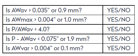
(i) Groove WidthIf the average width of the measured groove widths exceed 0.035” (0.889 mm) then the club is non-conforming.If any single measured groove width exceeds 0.039” (1.0 mm) then the club is non-conforming.(ii) Groove SeparationThe pitch of the grooves, as described in Section 8, must not be less than four times the width. Thus, the grooves do not conform if P/AWav is less than 4.0.P – AWav must not be less than 0.075” or 1.9 mm.(iii) Groove ConsistencyThe difference in width between the second widest and the second narrowest groove must not exceed 0.004” or 0.1 mm. The grooves do not conform if AWvar is greater than 0.004” or 0.1 mm.11. It is recognized that groove measurements made, as these are, at one point along the length of the grooves, are sensitive to small manufacturing errors. Therefore, if a club fails on one of the above criteria, it should not immediately be declared non-conforming; but the whole measuring procedure should be repeated at a slightly different part of the face (say 0.394” or 10 mm to the other side of the centre of a club face from the first set). For a club to be declared non-conforming, it must fail to meet the same specification on both sets of measurements. In the case of a single overwidth groove (AWmax), the same groove must be overwidth on both measurements.
1.1h
Irregular or Unusual Grooves
12. For grooves with markedly varying separation (See Figure 6 below), the above procedures need modification, though the same measuring technique applies. In general, the concept of average groove pitch has to be abandoned and groove pitch (or separation) taken for individual pairs of adjacent grooves. In the sample illustrated, the club face would need to be divided into two or even three separation regions.Difficult cases should be submitted to the The R&A or USGA for a ruling.
Fig 6: Non-uniform grooves
Example of non-uniform spacing where the 'average' pitch is meaningless.
13. For used clubs with worn grooves the width measurements must be made on grooves which are not worn. These can nearly always be found near the toe of the club, or high on the face. Avoid the extreme end of the grooves since the width sometimes varies there. If it is impossible to find ten unworn grooves, measure as many as possible and make the necessary modifications to the calculation of average width.If the grooves on a used club have been deliberately altered by filing or the use of a groove scoring tool, then the club should be treated as though it were new and the grooves measured near the centre of the face.14. Very occasionally grooves will be found which are either very shallow, or have sides which make an angle of less than 30° to the horizontal. In these circumstances the marking tool will not work properly and the club should be submitted to The R&A or USGA for a ruling, although it may be possible to give an “on the spot” conforming ruling if the grooves clearly conform.
1.1i
SUMMARY OF GROOVE MEASURING PROCEDURE
(The bracketed numbers refer to the corresponding paragraphs in Supplementary Paper B – “Guidance on the Measurement of Grooves on Club Faces”.)1. Clean club face [1]; ink the edges of ten grooves in a 5mm wide band. [2]2. Check marking tool [1]; use it as described in full instructions [3] to scrape the edges of the inked grooves.3. Use the magnifier to measure the width of all ten grooves, and record on the results sheet. [4, 5, 6, 7]4. Calculate and record on the results sheet the average width, the greatest width and the width variation. [7]5. Calculate and record the adjusted widths which allow for the uncertainties of measurement. [9] 6. Use the ruler to measure a span of ten grooves (e.g. from groove 1 to groove 11 (not 10), or 2 to 12). [8] (OR, if preferred, use the magnifier to measure a four groove span. [8])7. Calculate and record the average groove-to-groove pitch. [8] 8. Calculate and record the pitch to width ratio, remembering to use the adjusted width; also calculate the separation (pitch minus adjusted width). 9. Using quantities calculated in 5 and 8 above, answer the questions near the foot of the results sheet to determine whether the grooves conform. [10, 11] Manufacturers are advised to use actual widths in these calculations. [9] 10. Follow the steps on the results sheet to reach a decision on the club, if necessary repeating the measurement. [11]* * *NB. Consult the full instructions for grooves with inconsistent spacing, or other unusual features [12, 13, 14].
1.1j
ABBREVIATED PROCEDURE FOR GROOVE MEASUREMENTS
It may be quite acceptable, for an experienced user of the measuring equipment, to abbreviate the measuring procedure on clubs whose grooves clearly lie well within the specified dimensions.First, inspect the club face by eye, and check whether the grooves are: (a) unevenly spaced (b) of unequal width (c) unusually wide (d) unusually close together.If any of these conditions apply, then the full measurement must be carried out.If none of these conditions apply, then the following abbreviated procedure may save some time and effort without affecting the outcome:Ink and mark three grooves, and measure their width with the magnifier. Take the greatest of the three measured widths and add 0.002” or 0.05 mm to it. Call this W(+).(For example, if the three widths were measured as 0.030” or 0.75 mm, 0.033” or 0.80 mm and 0.030” or 0.75 mm, then W(+) would be 0.033” or 0.85 mm).Then measure the pitch, P, with the steel ruler as described in the full procedure.Then check: Is W(+) less than 0.035” or 0.9 mm? Is W(+) less than P/4? Is P-W(+) greater than 0.075” or 1.9 mm?If all the answers are YES (and you have carried out the initial visual check), the club is certain to meet the requirements of the full tests; and it may be deemed to conform without further testing.If any of the answers are NO, the full measurement must be carried out.IF YOU HAVE ANY DOUBT, CARRY OUT THE FULL MEASUREMENT.
1.1k
GROOVE MEASUREMENT TABLE AND REPEAT GROOVE MEASUREMENT TABLE
GROOVE MEASUREMENT ON (club name)DATE: MEASURED BY:1. WIDTH OF INDIVIDUAL GROOVESSecond greatest minus second smallest width (Wvar) = in or mmTo give benefit of measuring error to the club, subtract 0.002” or 0.05mm(the maximum error) from these widths to give the corresponding “adjusted widths”:AWav = in or mm AWmax = in or mm AWvar = in or mmTHESE ARE THE WIDTHS USED IN ALL CALCULATIONS HEREAFTER2. PITCH OF GROOVESSpan of ten grooves (measured by steel ruler) = in or mmTherefore pitch, P = /10 = in or mm{ALTERNATIVELY: Span of four grooves (measured by magnifier) = in or mmTherefore pitch, P = /4 = in or mm Note pitch measurement in left hand box below. Calculate and enter the other quantities.P = in or mm P/AW = in or mm P-AWav = in or mm3. TEST FOR CONFORMANCEIF ALL ANSWERS ARE ‘NO’, OR IF ‘YES’ ANSWERS ARISE ONLY WHERE THE FIRST MEASUREMENT GAVE ‘NO’, GROOVES ON CLUB CONFORM. No further measurements are needed.IF ANY ‘YES’ ANSWERS ARE REPEATS OF THOSE IN FIRST MEASUREMENT, THE GROOVES DO NOT CONFORM.Circle the appropriate word: CONFORMING NON-CONFORMINGREPEAT GROOVE MEASUREMENT ON (club name)DATE: MEASURED BY:1. WIDTH OF INDIVIDUAL GROOVESSecond greatest minus second smallest width (Wvar) = in or mmTo give benefit of measuring error to the club, subtract 0.002” or 0.05mm(the maximum error) from these widths to give the corresponding “adjusted widths”:AWav = in or mm AWmax = in or mm AWvar = in or mmTHESE ARE THE WIDTHS USED IN ALL CALCULATIONS HEREAFTER2. PITCH OF GROOVESSpan of ten grooves (measured by steel ruler) = in or mmTherefore pitch, P = /10 = in or mm{ALTERNATIVELY: Span of four grooves (measured by magnifier) = in or mm Therefore pitch, P = /4 = in or mmNote pitch measurement in left hand box below. Calculate and enter the other quantities.P = in or mm P/AW = in or mm P-AWav = in or mm3. TEST FOR CONFORMANCEIF ALL ANSWERS ARE ‘NO’, OR IF ‘YES’ ANSWERS ARISE ONLY WHERE THE FIRST MEASUREMENT GAVE ‘NO’, GROOVES ON CLUB CONFORM. No further measurements are needed.IF ANY ‘YES’ ANSWERS ARE REPEATS OF THOSE IN FIRST MEASUREMENT, THE GROOVES DO NOT CONFORM.Circle the appropriate word: CONFORMING NON-CONFORMING
1.1l
Groove Depth
In order to help Officials rule on the groove depth “in the field”, a simple gauge has been developed which is available from The R&A or USGA at a reasonable cost.The gauge consists of a small circular disc which has a raised, thin ridge running across the diameter. This ridge measures exactly 0.022 inches (0.559 mm) in depth, which offers a small tolerance suitable for measurements carried out “in the field”.
1.1m
Method of Use
In order to judge the depth of a groove on a club, the disc should be placed onto the face with the ridge running along the inside of the groove. The user should then apply pressure to the disc, on both sides of the ridge, to see if the disc will rock from side to side.If the disc does noticeably rock, then the groove cannot be too deep. It means that the depth of the ridge is greater that the depth of the groove.If, on the other hand, the disc lies flush with the face and cannot be rocked, it means that the groove is likely to be too deep.In both instances above, the gauge should be used on at least six grooves within the “impact area” of the face (or near the toe for club faces which are quite worn).If 50% or more of the grooves tested appear to be too deep when using this gauge, the club should not be carried.
1.1n
Punch Marks
Punch marks are almost always circular in shape and, therefore, the area of the punch mark can be determined using the calculation πr2 (where π~ 3.142). The radius of the punch mark can be measured using a magnifier as can the separation of two punch marks – measured centre to centre. The depth measurement would require the use of a depth probe. While the depth of a punch mark is limited to 0.040 inches (1.02 mm) within the Rules, it is highly unlikely that this measurement would ever be queried “in the field”.
1.1o
Definition of "Impact Area" - for clubs manufactured prior to 1 January 2010
For iron clubs, the “impact area” is deemed to be that part of the face which lies within 0.79 inches (20 mm) either side of the vertical centre line of the face, but excluding strips 0.25 inches (6.25 mm) wide from the top and bottom edges.For metal wood clubs, the shape of the impact area is generally based on the traditional insets used in persimmon type wood clubs. Figure 7 illustrates the shape and dimensions of this area.
Fig 7: Impact area for metal woods (for pre-2010 clubs)
(a) Guideline is based in style of the traditional inset used in persimmon wood clubs. (b) Metal wood head showing size and shape of impact area. The word "Premier" does not encroach the area, therefore the club is conforming.
The height (h) of the trapezium is used to fix the horizontal dimensions namely "1/2h” at the top and “h” at the base. This ensures that all impact areas are similar.
 3. When the ink is dry take the marking tool, hold it like a pencil at about 45° to the club face and insert the pointed corner of its tip into one of the blackened grooves. (See Figure 2 below.) Using firm but not too heavy pressure, pull the tool along the groove for about 0.25” (5 mm). Two narrow bright lines of exposed metal should now be visible, one on each side of the groove denoting the position of the edges of the grooves. (See Figure 3).
Do the same for all ten blackened grooves.
3. When the ink is dry take the marking tool, hold it like a pencil at about 45° to the club face and insert the pointed corner of its tip into one of the blackened grooves. (See Figure 2 below.) Using firm but not too heavy pressure, pull the tool along the groove for about 0.25” (5 mm). Two narrow bright lines of exposed metal should now be visible, one on each side of the groove denoting the position of the edges of the grooves. (See Figure 3).
Do the same for all ten blackened grooves.


 This measurement can be made either with the steel ruler or with the magnifier; but, in most cases, the steel ruler is the more convenient. Measure the left edge to left edge distance from groove 1 to groove 11 (or 2 to 12 etc), and divide this distance by 10 to arrive at the pitch, P. If a ten groove span is not available, then nine or eight will be satisfactory (but remember to divide by the appropriate number to find P).
Alternatively, and this is the only option if a span of fewer than eight grooves is available, you can use the magnifier. Measure the distance from one edge of groove 1 to the corresponding edge of groove 5. The best way to do this is to position the long zero line of the magnifier scale on the left edge of groove 3 then read off the distances on either side of it to grooves 1 and 5 and add them together. You can, of course, use any two grooves spaced four apart (e.g. 3 and 7, or 6 and 10); indeed, it may be as well to check your first measurement by repeating the procedure with another such pair of grooves.
It is good enough to make this measurement to the nearest 0.005 inches or 0.1 mm. Then divide the measured span of four grooves by 4 to give the pitch, P.
Whichever method is used, the object is to get the best possible measure of the average groove pitch (P).
At this stage it may be worth checking your average by measuring the pitch from one groove to the next one, e.g. grooves 1 to 2, or 5 to 6. If these measurements differ from the average by more than 0.005 or 0.1 mm, then either you calculated the average incorrectly (check it), or the grooves are unevenly spaced. In the latter event you must measure the grooves differently (see Section 14).
This measurement can be made either with the steel ruler or with the magnifier; but, in most cases, the steel ruler is the more convenient. Measure the left edge to left edge distance from groove 1 to groove 11 (or 2 to 12 etc), and divide this distance by 10 to arrive at the pitch, P. If a ten groove span is not available, then nine or eight will be satisfactory (but remember to divide by the appropriate number to find P).
Alternatively, and this is the only option if a span of fewer than eight grooves is available, you can use the magnifier. Measure the distance from one edge of groove 1 to the corresponding edge of groove 5. The best way to do this is to position the long zero line of the magnifier scale on the left edge of groove 3 then read off the distances on either side of it to grooves 1 and 5 and add them together. You can, of course, use any two grooves spaced four apart (e.g. 3 and 7, or 6 and 10); indeed, it may be as well to check your first measurement by repeating the procedure with another such pair of grooves.
It is good enough to make this measurement to the nearest 0.005 inches or 0.1 mm. Then divide the measured span of four grooves by 4 to give the pitch, P.
Whichever method is used, the object is to get the best possible measure of the average groove pitch (P).
At this stage it may be worth checking your average by measuring the pitch from one groove to the next one, e.g. grooves 1 to 2, or 5 to 6. If these measurements differ from the average by more than 0.005 or 0.1 mm, then either you calculated the average incorrectly (check it), or the grooves are unevenly spaced. In the latter event you must measure the grooves differently (see Section 14). 13. For used clubs with worn grooves the width measurements must be made on grooves which are not worn. These can nearly always be found near the toe of the club, or high on the face. Avoid the extreme end of the grooves since the width sometimes varies there. If it is impossible to find ten unworn grooves, measure as many as possible and make the necessary modifications to the calculation of average width.
If the grooves on a used club have been deliberately altered by filing or the use of a groove scoring tool, then the club should be treated as though it were new and the grooves measured near the centre of the face.
14. Very occasionally grooves will be found which are either very shallow, or have sides which make an angle of less than 30° to the horizontal. In these circumstances the marking tool will not work properly and the club should be submitted to The R&A or USGA for a ruling, although it may be possible to give an “on the spot” conforming ruling if the grooves clearly conform.
13. For used clubs with worn grooves the width measurements must be made on grooves which are not worn. These can nearly always be found near the toe of the club, or high on the face. Avoid the extreme end of the grooves since the width sometimes varies there. If it is impossible to find ten unworn grooves, measure as many as possible and make the necessary modifications to the calculation of average width.
If the grooves on a used club have been deliberately altered by filing or the use of a groove scoring tool, then the club should be treated as though it were new and the grooves measured near the centre of the face.
14. Very occasionally grooves will be found which are either very shallow, or have sides which make an angle of less than 30° to the horizontal. In these circumstances the marking tool will not work properly and the club should be submitted to The R&A or USGA for a ruling, although it may be possible to give an “on the spot” conforming ruling if the grooves clearly conform.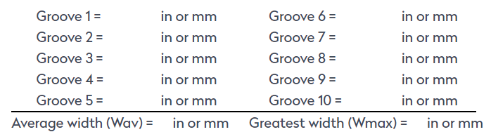
 The height (h) of the trapezium is used to fix the horizontal dimensions namely "1/2h” at the top and “h” at the base. This ensures that all impact areas are similar.