
Opening Golf to the World
Print section
2Conformance of Clubs
2
Conformance of Clubs
2
Conformance of Clubs
The rules and specifications regarding golf clubs are divided into five separate categories, describing the requirements that apply to each. The five categories are:
- Club (General)
- Shaft
- Grip
- Clubhead
- Club Face.
2.1
Clubs
2.1a
General
A club is an implement designed to be used for striking the ball and generally comes in three forms: woods, irons and putters distinguished by shape and intended use. A putter is a club with a loft not exceeding ten degrees designed primarily for use on the putting green.
The terms “wood” and “iron” refer to the general shape of the clubhead. A wood club is one where the head is relatively broad from face to back, and it can be made of a variety of materials. An iron club is one where the head is relatively narrow from face to back, and it is usually made of steel. While it can be challenging to distinguish between these two club types because of the popularity of “hybrid”, rescue and utility clubs, the determination of whether a club is a “wood” or an “iron” and, in turn, which Equipment Rules apply to it is dealt with based on an overall assessment of the shape and size of the head.
By definition, the loft of a putter must not be greater than 10 degrees. Putters are permitted to have negative loft. However, a negative loft exceeding a magnitude of 15 degrees would not be considered “traditional and customary in form and make” (see Section 1a(i) below).
The Equipment Rules rarely distinguish between wood and iron clubs (see Section 4b, Dimensions, Volume and Moment of Inertia, for the main example of different treatment), but there are various instances throughout the Equipment Rules where certain specifications do not apply to putters or exceptions may be made for putters. These differences will be highlighted at the appropriate places throughout the Equipment Rules.
Probably as a consequence of these differences, confusion often exists as to which Equipment Rules apply to “chippers”. A “chipper” is an iron club designed primarily for use off the putting green, generally with a loft greater than ten degrees. As most players adopt a “putting stroke” when using a chipper, there can be a tendency to design the club as if it was a putter. To eliminate confusion, the Equipment Rules which apply to chippers include:
- The shaft must be attached to the clubhead at the heel (Section 2c);
- The grip must be circular in cross-section (Section 3b(i)) and only one grip is permitted (Section 3c);
- The clubhead must be generally plain in shape (Section 4a) and have only one striking face (Section 4d); and,
- The face of the club must conform to the specifications with respect to hardness, surface roughness, material, markings in the impact area and dynamic properties (Sections 4c and 5).
- The length of the club must follow the guidelines for chippers specified in the table located in Section 1c.
- Temporary, non-permanent attachments to the shaft such as decals for identification - such attachments, for identification only, may also be permitted on the clubhead (other than the face). Additionally, tape to protect the shaft is permitted. However, these attachments must not be usable for any other purpose (e.g. alignment).
- Temporary, non-permanent attachments to the shaft (e.g. “clip-on” devices), provided such items do not excessively protrude from the shaft, their cross-section conforms to the shape of the shaft and they are sufficiently fixed. Other “clip-on” devices that do not conform to the shape of the shaft (e.g. a club “prop” for use in wet weather) may be attached to the shaft between shots but must be removed prior to making a stroke.
- Other material added to the shaft, such as for alignment purposes, provided it is considered semi-permanent. However, such applications must not breach Rule 4.3. “Semi-permanent” is interpreted to mean durable and not easily removable. Additionally, it must not be re-usable and/or must be essentially destroyed upon removal.
- Temporary, non-permanent attachments to the butt end of the grip such as tee pegs, ball markers or ball retrieving devices, provided:
- such items do not cause the grip to be considered moulded for the hands or create a bulge or waist in the grip; and
- the outer diameter of the item is less than or equal to the outer diameter of the butt end of the grip and the item does not extend beyond the butt end of the grip by more than 2 inches (50.8mm).
- Other temporary, non-permanent attachments to any part of the grip other than the butt end, provided such items are removed prior to making a stroke. However, tape or gauze applied to the full length of the grip is permitted provided the grip conforms in its modified state and the underlying grip conforms.
- Attachments to the clubhead (other than the face), such as protective coverings, decorative items or alignment aids, provided the item is semi-permanent. However, such items must not excessively protrude from the clubhead and must conform to the shape of the clubhead. Also, for driving clubs, such attachments must not serve to cause any confusion with the correct identification of a club on the List of Conforming Driver Heads. Such attachments should, therefore, be subtle, plain in appearance and discreetly positioned. Permanent additions to a clubhead would be considered part of the head and, therefore, the head, in its modified state, would have to conform to Part 2, Section 4 of the Equipment Rules (i.e. for dimensions and “plain in shape”).
2.1b
Adjustability
All clubs may incorporate features for weight adjustment. Other forms of adjustability may also be permitted upon evaluation by The R&A or USGA.
The following requirements apply to all permissible methods of adjustment:
(i) the adjustment cannot be readily made;
(ii) all adjustable parts are firmly fixed and there is no reasonable likelihood of them working loose during a round; and
(iii) all configurations of adjustment conform with the Rules.
During a round, the performance characteristics of a club must not be purposely changed by adjustment or by any other means (see Rule 4.1a(3) of the Rules of Golf).
(i) General
All clubs may be designed to be adjustable for many different characteristics – for example, weight, length, lie and loft. In order to preserve the integrity of Rule 4.1a(3) of the Rules of Golf (“Deliberately” Changing Club’s Performance Characteristics During Round), the Equipment Rules clearly state that it must not be too easy for a player to make adjustments during a round and that the mechanism must be firmly fixed, with little chance of it working loose. All adjustment mechanisms must comply with the following requirements:
• Method of Adjustment
Adjustments must require the use of a special tool, such as an Allen key, a Phillips screwdriver or a custom made device. It must not be possible to make the adjustment just by using the fingers or some other object which would normally be kept in a golfer’s pocket, for example a coin or a pitch-mark repair tool.
• Unusable Unless Locked or Fully Tightened
If, as is often the case, a screw is used to fix the mechanism, the club must, for all practicable purposes, be unusable without the screw being in place and tightly fixed. One exception to this “unusable” requirement is for a long putter with a shaft which dismantles into two shorter lengths for travel purposes. Here, a screw together (“pool cue”) joint is permitted, in combination with an Allen key screw, or similar, which penetrates the threaded section of the joint by at least half way. The existence of both the threaded joint and the fixing screw potentially renders the putter usable, even when the screw is not tightened, or it is left out entirely. It also renders the putter potentially adjustable by hand. However, this exception was introduced as a specific concession for travel clubs.
• Friction Fit Mechanisms
Generally, friction fit adjustment mechanisms are not permitted because there is potential for them to be readily adjustable (i.e. the mechanism could be sufficiently tightened such that the club is usable, but not quite enough to prohibit it from being adjustable by hand). However, a friction fit mechanism which can be only locked and unlocked and is fixed in its locked state and unusable in its unlocked state, may be permitted upon evaluation.
• Discrete Steps
A mechanism that allows for an adjustment to be made in discrete steps may be permitted provided all other Equipment Rules and specifications are satisfied. Without the adjustment mechanism locked in place, the club must essentially be unusable.
The above restrictions have been included in the Equipment Rules in order to encourage the player to make all of the necessary adjustments to his or her clubs before starting the round, and to protect the player from either unwittingly or purposely making adjustments during a round.
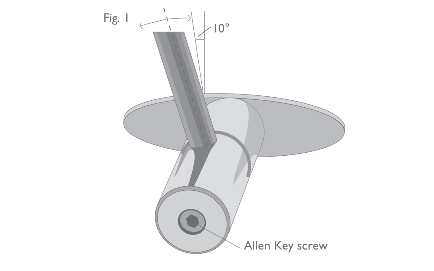
When assessing the conformity of an adjustable club, it is important to remember the third condition listed in Part 2, Section 1b, and to check that it cannot be adjusted into a position which does not conform to the Equipment Rules. For example, a putter which is adjustable for lie must not be capable of being adjusted into a position where the shaft diverges from the vertical by less than 10 degrees (see Section 1d, below), or any other position which would render the club non-conforming (see Figure 1).
 (ii) Adjustability for Weight
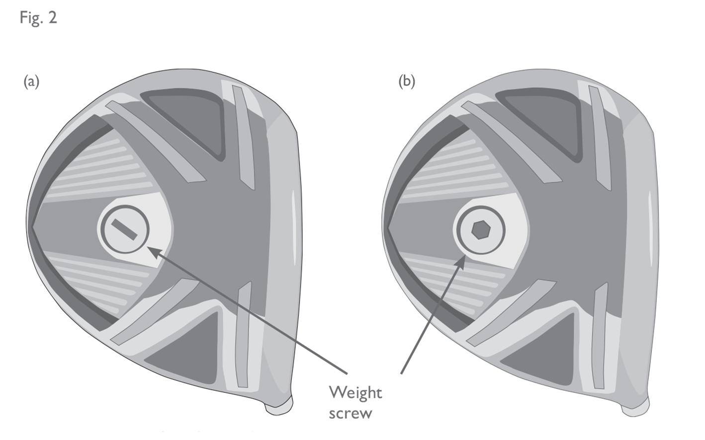
All clubs may be designed to be adjustable for weight, provided the adjustment mechanism conforms to the conditions described in Section 1b of the Equipment Rules. Examples of what would and would not be permitted are illustrated in Figure 2.
As noted in Section 1a, with respect to adjustments for weight, the only exception to the conditions described in Section 1b(i) above is the addition or removal of lead tape. This is a practice which pre-dates the introduction of the adjustability rules and is permitted on ‘traditional’ grounds. The addition, removal or alteration of lead tape during a round is not permitted (see Rule 4.1a(3) of the Rules of Golf).
(iii) Adjustability for Length
• All Clubs
All clubs may be adjustable for length, provided the adjustment mechanism conforms to the specifications already described and is consistent with other Equipment Rules.
Integrated mechanisms are permitted, provided the bending and twisting properties of the shaft remain substantially the same and the grip remains conforming. Mechanisms externally attached to the grip are not permitted.
Telescopic Mechanisms that can be fully extended into a locked position for use and collapsed for travel purposes may be permitted. However, the club must not be usable in its collapsed, unlocked state.
• Putters
Non-integrated mechanisms attached to the shaft may be permitted for putters only, provided that:
(ii) Adjustability for Weight
All clubs may be designed to be adjustable for weight, provided the adjustment mechanism conforms to the conditions described in Section 1b of the Equipment Rules. Examples of what would and would not be permitted are illustrated in Figure 2.
As noted in Section 1a, with respect to adjustments for weight, the only exception to the conditions described in Section 1b(i) above is the addition or removal of lead tape. This is a practice which pre-dates the introduction of the adjustability rules and is permitted on ‘traditional’ grounds. The addition, removal or alteration of lead tape during a round is not permitted (see Rule 4.1a(3) of the Rules of Golf).
(iii) Adjustability for Length
• All Clubs
All clubs may be adjustable for length, provided the adjustment mechanism conforms to the specifications already described and is consistent with other Equipment Rules.
Integrated mechanisms are permitted, provided the bending and twisting properties of the shaft remain substantially the same and the grip remains conforming. Mechanisms externally attached to the grip are not permitted.
Telescopic Mechanisms that can be fully extended into a locked position for use and collapsed for travel purposes may be permitted. However, the club must not be usable in its collapsed, unlocked state.
• Putters
Non-integrated mechanisms attached to the shaft may be permitted for putters only, provided that:
Fig 1: Adjustability for lie
This putter is adjustable for lie - but must not be adjustable into a position where the shaft measures less than 10° from the vertical.
Fig 2: Adjustability for weight
(a) Mechanism can be adjusted by a coin (non-conforming). (b) Mechanism requires the use of an Allen key (conforming).
- The mechanism is generally circular in cross-section with a maximum cross-sectional dimension of 1 inch and a maximum length of 2 inches;
- If the mechanism is situated between two grips, both grips are non-tapered, the end of the mechanism effectively touches the butt end of the lower grip, the cross-sectional dimension of the mechanism is less than or equal to the maximum cross-sectional dimension of the grips, and the mechanism is at least 1.5 inches in length;
- If the mechanism is situated below a single grip or below the lower grip of a putter with two grips, the top of the mechanism is at least 2 inches from the tip end of the grip. Exception: If the size and shape of the mechanism is consistent with the tip end of the grip or the outer diameter of the mechanism is less than the outer diameter of the grip, the mechanism can effectively touch the tip end of the grip.
2.1c
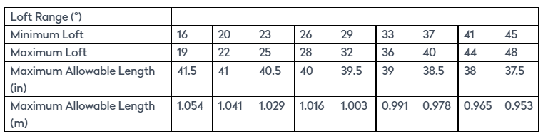
Length
Fig 3: Measurement of club length (woods and irons)
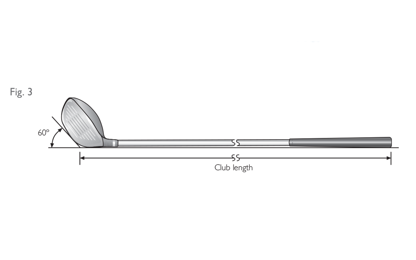
Fig 4: Measurement of club length (putters)
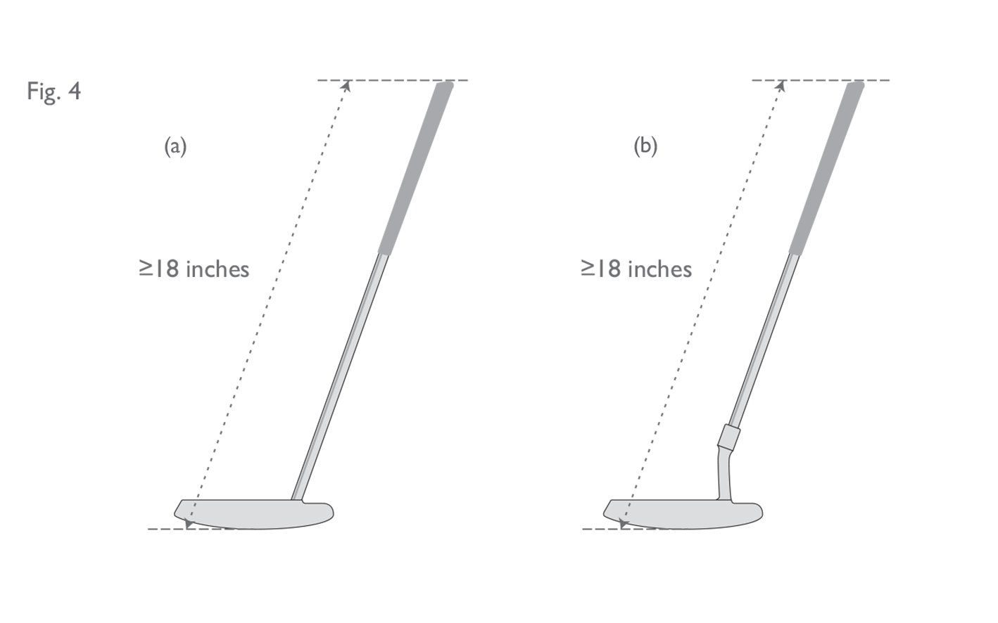
(a) This putter has a straight shaft attached to the clubhead. The measurement for club length follows the axis of the shaft and extends all the way down to the sole. (b) The shaft of this putter is attached to the head via a neck. The measurement for club length does not follow the axis of the bend in the neck, but follows a straight line extension of the straight part of the shaft all the way to the sole.
2.1d
Alignment
When the club is in its normal address position the shaft must be so aligned that:
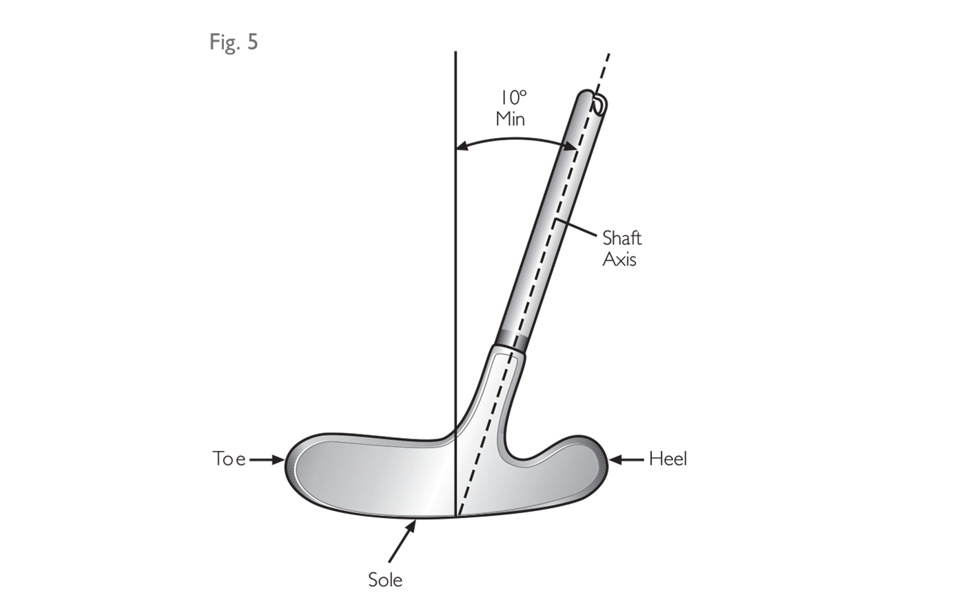
(i) the projection of the straight part of the shaft on to the vertical plane through the toe and heel must diverge from the vertical by at least 10 degrees (see Fig. 5). If the overall design of the club is such that the player can effectively use the club in a vertical or close-to-vertical position, the shaft may be required to diverge from the vertical in this plane by as much as 25 degrees;
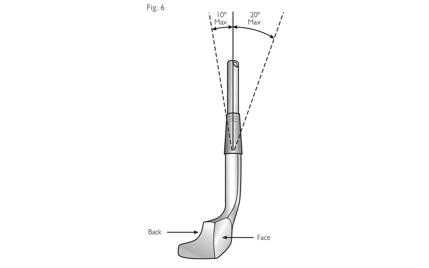
(ii) the projection of the straight part of the shaft on to the vertical plane along the intended line of play must not diverge from the vertical by more than 20 degrees forwards or 10 degrees backwards (see Fig. 6).
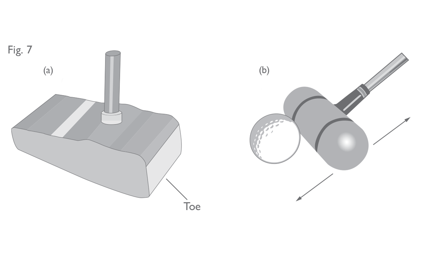
 This provision is particularly relevant to putters and it exists mainly as a means for disallowing croquet style putters (with vertical shafts) and shuffle-board style strokes (see Figure 7). It also seeks to limit the potential for more standard putters from being used effectively in a vertical or near-vertical position using a pendulum-style motion.
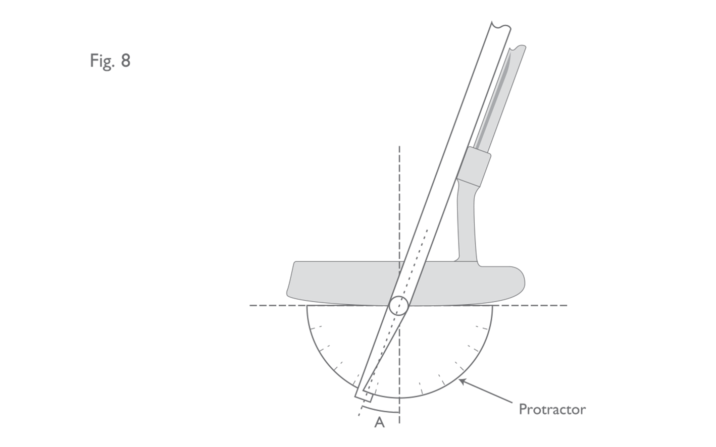
 For most putters, the “normal address position” is determined by the geometry of the head. The head would be placed on a horizontal flat surface, with the sole touching that surface at a point directly below the centre of the face. The shaft angle would then be measured with the head in this position (see Figure 8).
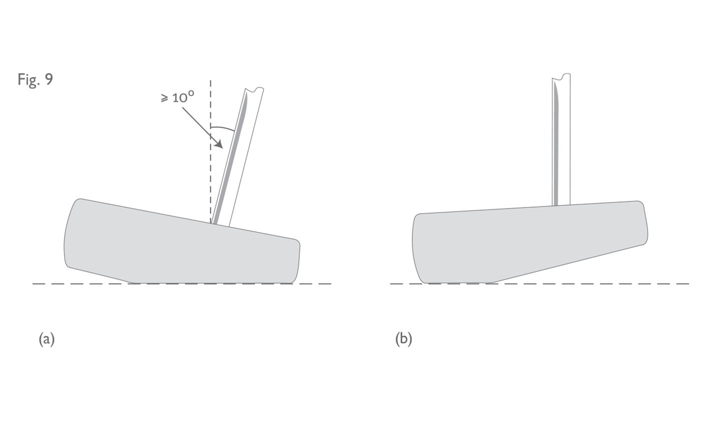 If the putter head shape or weight distribution is very asymmetric, it may be necessary to make a subjective judgement as to where the effective centre of the face is and then to sole the club directly below that point. The position of the head in this instance might not always be the position that was intended when the club was designed, but in some cases a judgement has to be made based on how the club could feasibly and effectively be used (see Figure 9).
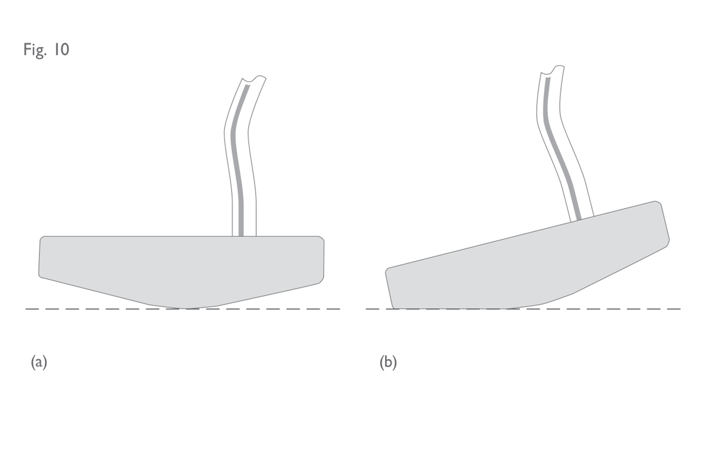
The same subjectivity may also be needed when confronted with a putter which has a very curved sole (see Figure 10). As before, the conformance evaluation would take into account not only the manner in which the putter is designed to be used, but also the way it could feasibly and effectively be used, given the geometry of the head as well as other unique characteristics of the overall design. This interpretation is particularly relevant to long-shafted putters with very curved or multi-planed soles – but standard length putters of 34-38 inches can also be subjected to this assessment
If the putter head shape or weight distribution is very asymmetric, it may be necessary to make a subjective judgement as to where the effective centre of the face is and then to sole the club directly below that point. The position of the head in this instance might not always be the position that was intended when the club was designed, but in some cases a judgement has to be made based on how the club could feasibly and effectively be used (see Figure 9).
The same subjectivity may also be needed when confronted with a putter which has a very curved sole (see Figure 10). As before, the conformance evaluation would take into account not only the manner in which the putter is designed to be used, but also the way it could feasibly and effectively be used, given the geometry of the head as well as other unique characteristics of the overall design. This interpretation is particularly relevant to long-shafted putters with very curved or multi-planed soles – but standard length putters of 34-38 inches can also be subjected to this assessment
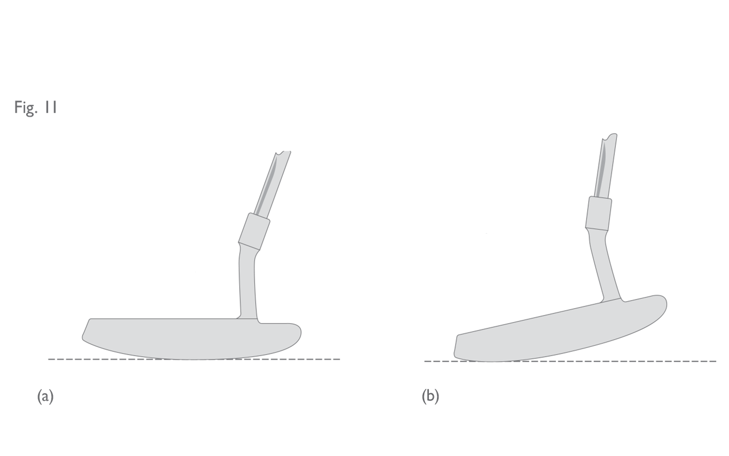
 It should be noted that all putters can usually be positioned in such a way that the shaft diverges from the vertical by less than 10° or even to a position where the shaft itself is vertical. Also, it is unusual for the sole of a putter to be completely flat all the way from heel to toe. When faced with a ruling of this kind, the decision should not be based on whether a player uses the putter with the shaft in a position less than 10° – but whether the putter design facilitates this (see Figure 11).
 If the overall design of a putter is such that a player can putt effectively with the shaft in a vertical or near-vertical position, it would be ruled contrary to Part 2, Section 1d, even if the shaft angle does satisfy the 10 degree Rule when the putter is in its “normal address position”. The shaft angle on such a putter would be required to be increased up to as much as 25 degrees. In assessing whether a putter can be used effectively in such a position and in order to determine what the shaft angle should be increased to, the combination of all of the following features must be considered:
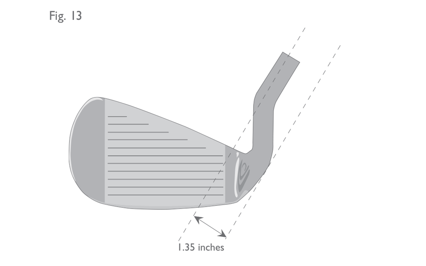
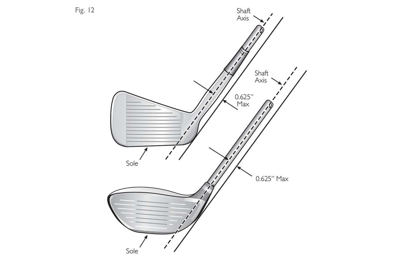 The intent of the provision is to prevent centre shafted clubs (see Section 2c below – “Attachment to the Clubhead”), and the measurement of an iron club is illustrated in Figure 13.
 It is worth highlighting that the heel portion of the club extends from the face all the way to the back of the head. Therefore, for unusually shaped heads (e.g. flared or square shaped), where the outermost part of the heel may be further back from the face than for more traditionally shaped heads, the measurement will be completed at that point.
It is also worth stressing that, in most cases, the shaft of a putter may be attached at any point on the clubhead (see Section 2c).
It is worth highlighting that the heel portion of the club extends from the face all the way to the back of the head. Therefore, for unusually shaped heads (e.g. flared or square shaped), where the outermost part of the heel may be further back from the face than for more traditionally shaped heads, the measurement will be completed at that point.
It is also worth stressing that, in most cases, the shaft of a putter may be attached at any point on the clubhead (see Section 2c).
Fig 5: Shaft Angle - lie
Fig 6: Shaft Angle - along line of play
Fig 7: Non-conforming clubs due to shaft angle
(a) This putter has a vertical shaft and a flat toe – ideal for croquet-style strokes (non-conforming). (b) This ‘shuffle-board’ type putter has a cylindrical shaped head that can slide easily across the ground. The player stands behind the ball, facing the hole and “pushes”. The shaft diverges from the vertical by more than 10° in the backwards plane (non-conforming).
Fig 8: Measuring the angle of a putter shaft
For this putter to conform, angle A must measure at least 10°.
Fig 9: Club with asymmetric sole
(a) When the putter head is soled in this position, the shaft does diverge from the vertical by at least 10°. (b) However, when the same putter head is soled in this position, the shaft is vertical. Therefore, putter is non-conforming.
Fig 10: Putter with very curved sole
(a) When the putter head is soled in this position, the shaft angle is greater than 10°. (b) However, when the same putter head is grounded in this position, the shaft angle is less than 10°. Therefore, putter is non-conforming.
Fig 11: Putter with curved sole
(a) The sole of this putter is not considered to be ‘very curved’. Therefore, the normal address position is deemed to be in the centre of the face. (b) While the angle of the shaft from the vertical is less than 10° in this position, it is not considered to be a feasible address position. Therefore, the putter is conforming and, hence, the player can use it in this position.
- length of shaft;
- position of shaft attachment to head;
- angle of shaft in toe to heel plane and front to back plane;
- shape and weight distribution of head;
- curvature and shape of sole; and
- intent of the design.
Fig 12: Shaft axis to heel
Fig 13: Shaft axis/heel measurement
The distance between the heel and the plane containing the axis of the straight part of the shaft is greater than 0.625 inches (15.88 mm) on this iron club (non‑conforming).
2.2
Shaft
2.2a
Straightness
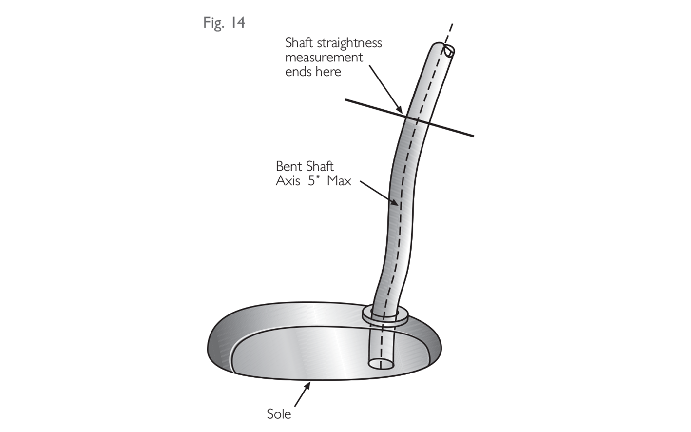
The shaft must be straight from the top of the grip to a point not more than 5 inches (127 mm) above the sole, measured from the point where the shaft ceases to be straight along the axis of the bent part of the shaft and the neck and/or socket (see Fig. 14).
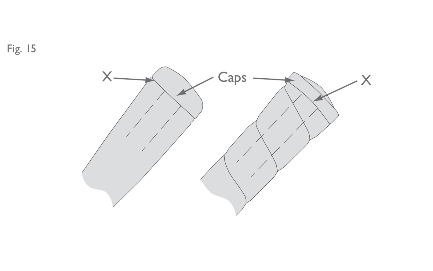
 This provision is interpreted to mean that the shaft must extend to the end of the grip, or at least that the grip should not extend beyond the top end of the shaft more than is necessary to accommodate the butt cap (see Figure 15).
 The “5-inch” measurement should be made using a pair of callipers (to measure the depth of the head at the point where the shaft is attached) and a flexible measuring tape, or a piece of string (to measure the length of any bend or bends in the shaft from the point where the shaft ceases to be straight) (see Figure 16).
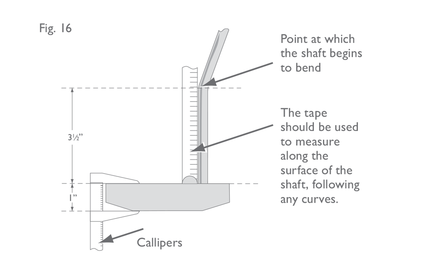 The point where the shaft ceases to be straight can be determined by placing a rigid steel ruler along the straight part of the shaft and marking the point where the shaft and the ruler are no longer in contact. This provision is particularly relevant to putters where the shaft is inserted directly into the head. (For putter heads that have a “neck” – see Section 2c).
Fig 14: Shaft straightness
Fig 15: Illustrations of "butt caps"
In both examples, the shaft must extend at least to point 'X'.
Fig 16: Measuring shaft straightness
2.2b
Bending and Twisting Properties
At any point along its length, the shaft must:
(i) bend in such a way that the deflection is the same regardless of how the shaft is rotated about its longitudinal axis; and
(ii) twist the same amount in both directions.
This provision effectively restricts shafts from being designed to have asymmetric properties, so that irrespective of how the club is assembled, or whichever way the shaft is orientated, it will make no difference to the performance of the club. Clause (i) is interpreted to mean that the way in which the shaft deflects must be the same regardless of its orientation. It is not simply a measure of the magnitude of deflection.
It is challenging to assess the conformance of a shaft in the field. However, a standard shaft with a circular cross-section would most likely conform unless there is specific evidence to the contrary (e.g. claims by the manufacturer which indicate non-conformance, including advertising claims). A shaft which is not symmetrical in all axes (e.g. a shaft with an oval or rectangular cross-section) would not normally be expected to conform to the Equipment Rules. Manufacturers of shafts with unusual cross-sections or other unique features should submit them to The R&A or USGA for a ruling prior to marketing and/or manufacturing. Whether such a ruling exists can be confirmed by contacting The R&A or USGA.
Many graphite shafts have a small “spine” or “spines” running along the length of the shaft which may make them bend a little differently depending on how they are oriented during installation. The existence of a small spine is generally regarded as being the result of normal manufacturing processes and therefore not a breach of Section 2b. As previously noted, The R&A and USGA recognizes that it is difficult to produce a perfectly symmetrical shaft. Therefore, provided that the shaft is manufactured with the intention of meeting the above requirement, a reasonable tolerance is applied when evaluating shafts for conformance.
Manufacturers of clubs may orientate or align shafts which have spines for uniformity in assembling sets or in an effort to make the shafts perform as if they were perfectly symmetrical. However, a shaft which has been orientated for the purpose of influencing the performance of a club, e.g. to correct wayward shots, would be contrary to the intent of this provision.
2.2c
Attachment to Clubhead
The shaft must be attached to the clubhead at the heel either directly or through a single plain neck and/or socket. The length from the top of the neck and/ or socket to the sole of the club must not exceed 5 inches (127 mm), measured along the axis of, and following any bend in, the neck and/or socket (see Fig. 17).
Exception for Putters: The shaft or neck or socket of a putter may be fixed at any point in the head.
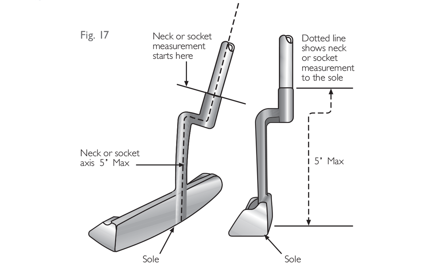 The most important points to remember here are that a club must only have one neck, that it must be “plain” and, in order to restrict elaborate shapes and curves, the length of the neck is limited to 5 inches (127 mm).
The interpretation of a “plain” neck is clarified as follows:
All clubs
The neck must not be shaped for any purpose, other than connecting the shaft to the head in a traditional manner. While a neck may contain features such as an adjustability mechanism, a method for damping vibration or an alignment line, it must not be unusually shaped in order to house or accommodate such a feature. For example, in most cases, lines which have been painted or lightly engraved onto an otherwise plain neck are permitted. However, a neck designed specifically to accommodate such lines or marks would be considered non-conforming. Small scale features, on an otherwise plain neck, which are purely for decorative purposes, and could not effectively perform, or be used for, another purpose, may also be permitted.
Woods
The above requirements also apply to woods, however there is some accommodation for the transition area between the head of a wood and its neck. This transition area must fit within a cylinder of a diameter and height of 1 inch (25.4 mm) measured from the base of the transition and parallel to the axis of the shaft. Any transition which satisfies this restriction should be permitted provided it does not contain any other non-plain feature (for example, holes or alignment bars).
NOTE: Some exceptions may be made for clubheads made of wood. Ferrules shaped to circumvent this interpretation are not permitted.
The measurement of the length of a neck should be made in the same way as a bend in the bottom of a shaft (see Section 2a and Figure 16).
The majority of necks are designed to have the shaft inserted into them, and this normally avoids any confusion as to where the neck begins. However, if the neck is inserted into the shaft, the measurement should be taken from the end of the shaft.
Figure 18 contains diagrams of various neck features which would not be permitted.
The most important points to remember here are that a club must only have one neck, that it must be “plain” and, in order to restrict elaborate shapes and curves, the length of the neck is limited to 5 inches (127 mm).
The interpretation of a “plain” neck is clarified as follows:
All clubs
The neck must not be shaped for any purpose, other than connecting the shaft to the head in a traditional manner. While a neck may contain features such as an adjustability mechanism, a method for damping vibration or an alignment line, it must not be unusually shaped in order to house or accommodate such a feature. For example, in most cases, lines which have been painted or lightly engraved onto an otherwise plain neck are permitted. However, a neck designed specifically to accommodate such lines or marks would be considered non-conforming. Small scale features, on an otherwise plain neck, which are purely for decorative purposes, and could not effectively perform, or be used for, another purpose, may also be permitted.
Woods
The above requirements also apply to woods, however there is some accommodation for the transition area between the head of a wood and its neck. This transition area must fit within a cylinder of a diameter and height of 1 inch (25.4 mm) measured from the base of the transition and parallel to the axis of the shaft. Any transition which satisfies this restriction should be permitted provided it does not contain any other non-plain feature (for example, holes or alignment bars).
NOTE: Some exceptions may be made for clubheads made of wood. Ferrules shaped to circumvent this interpretation are not permitted.
The measurement of the length of a neck should be made in the same way as a bend in the bottom of a shaft (see Section 2a and Figure 16).
The majority of necks are designed to have the shaft inserted into them, and this normally avoids any confusion as to where the neck begins. However, if the neck is inserted into the shaft, the measurement should be taken from the end of the shaft.
Figure 18 contains diagrams of various neck features which would not be permitted.
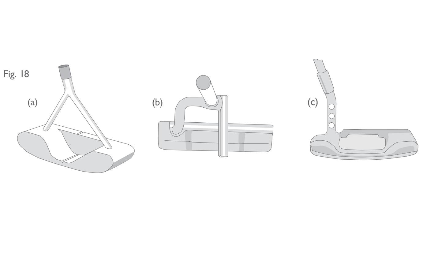
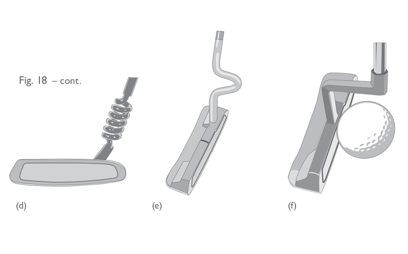
Fig 17: Length of neck
Fig 18 a b c: Examples of non-conforming necks
(a) Putter with two necks (non-conforming). (b) Putter with aiming bar attached to the neck (non-"plain", non-conforming). (c) Putter with holes through the neck (non-"plain", non-conforming).
Fig 18 d e f: Examples of non-conforming necks (cont)
(d) The length of this spiral neck is measured following the axis of the bends and is longer than 5 inches and non-"plain" (non-conforming). (e) Putter with forward protruding neck. If a neck protrudes forward of the face then the shaft connection must be made at the forward most point. This putter is contrary to that requirement (non-“plain”, non-conforming). (f) If the shaft or the neck of a putter is attached to the head near the centre of the face, it must protrude forward of the face by no more than 0.84 inches (the radius of a ball). The neck on this putter extends forward by more than half of the ball (non‑“plain”, non‑conforming).
2.3
The Grip
2.3a
Definition
The grip consists of material added to the shaft to enable the player to obtain a firm hold. The grip must be fixed to the shaft, must be straight and plain in form, must extend to the end of the shaft and must not be moulded for any part of the hands. If no material is added, that portion of the shaft designed to be held by the player must be considered the grip.
The grip is primarily for the purpose of assisting the player in obtaining a firm hold – so that the club does not slip or twist out of the player’s hands. However, the installation of a grip onto the shaft is optional.
When no material is added to the part of the shaft designed to be held by the player, the provisions relating to the grip take precedence over the provisions relating to the shaft. Therefore, the dimensions and cross-section of that area of the shaft could change (per Section 3b) and equal bending in any direction would not be required (so Section 2b does not apply in this case).
In order to accommodate both hands, the grip must be at least 7 inches (177.8 mm) in length. This also applies to clubs which have been designed to be used one-handed. For putters which have two grips, see Section 3c below.
Due to the nature of grips and the grip provisions, it is sometimes challenging to make a ruling without examining and comparing examples of other grips which are known to either conform or not conform. However, this is not something which would normally be possible in the field. It may help to remember that the overall consideration is that a grip “must not be moulded for any part of the hands”. If a certain feature on the grip enables the player to place his or her hands in exactly the same position every time, solely by feel, then it must be determined whether that feature renders the grip “moulded for the hands”. An extreme example of a grip which would be ruled “moulded for the hands” is the type of training grip often used to help beginners. However, a grip which has subtle changes in surface texture would usually be considered conforming. Likewise, printed markings which assist with the correct placement of the hands visually would normally be considered conforming. Most of the details contained in Sections 3b and 3c below serve to clarify and expand on this basic principle.
2.3b
Cross-section
(i) For clubs other than putters the grip must be circular in cross-section, except that a continuous, straight, slightly raised rib may be incorporated along the full length of the grip, and a slightly indented spiral is permitted on a wrapped grip or a replica of one.
(ii) A putter grip may have a non-circular cross-section, provided the cross-section has no concavity, is symmetrical and remains generally similar throughout the length of the grip. (See Section 3b(ii) explanation on p34).
(iii) The grip may be tapered but must not have any bulge or waist. Its cross‑sectional dimensions measured in any direction must not exceed 1.75 inches (44.45 mm).
(iv) For clubs other than putters the axis of the grip must coincide with the axis of the shaft.
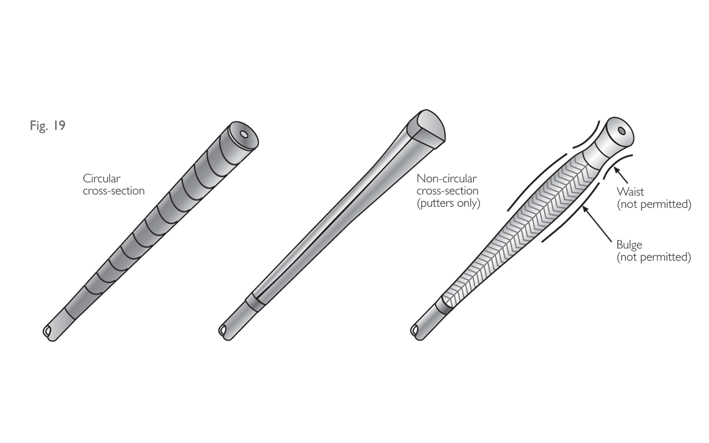 To take these each in turn:
(i) Circular Cross-section for Woods and Irons
Grips on woods and iron clubs are allowed to deviate from circular by having a slightly raised rib running along the full length of the grip (often called a “reminder rib”).
To take these each in turn:
(i) Circular Cross-section for Woods and Irons
Grips on woods and iron clubs are allowed to deviate from circular by having a slightly raised rib running along the full length of the grip (often called a “reminder rib”).
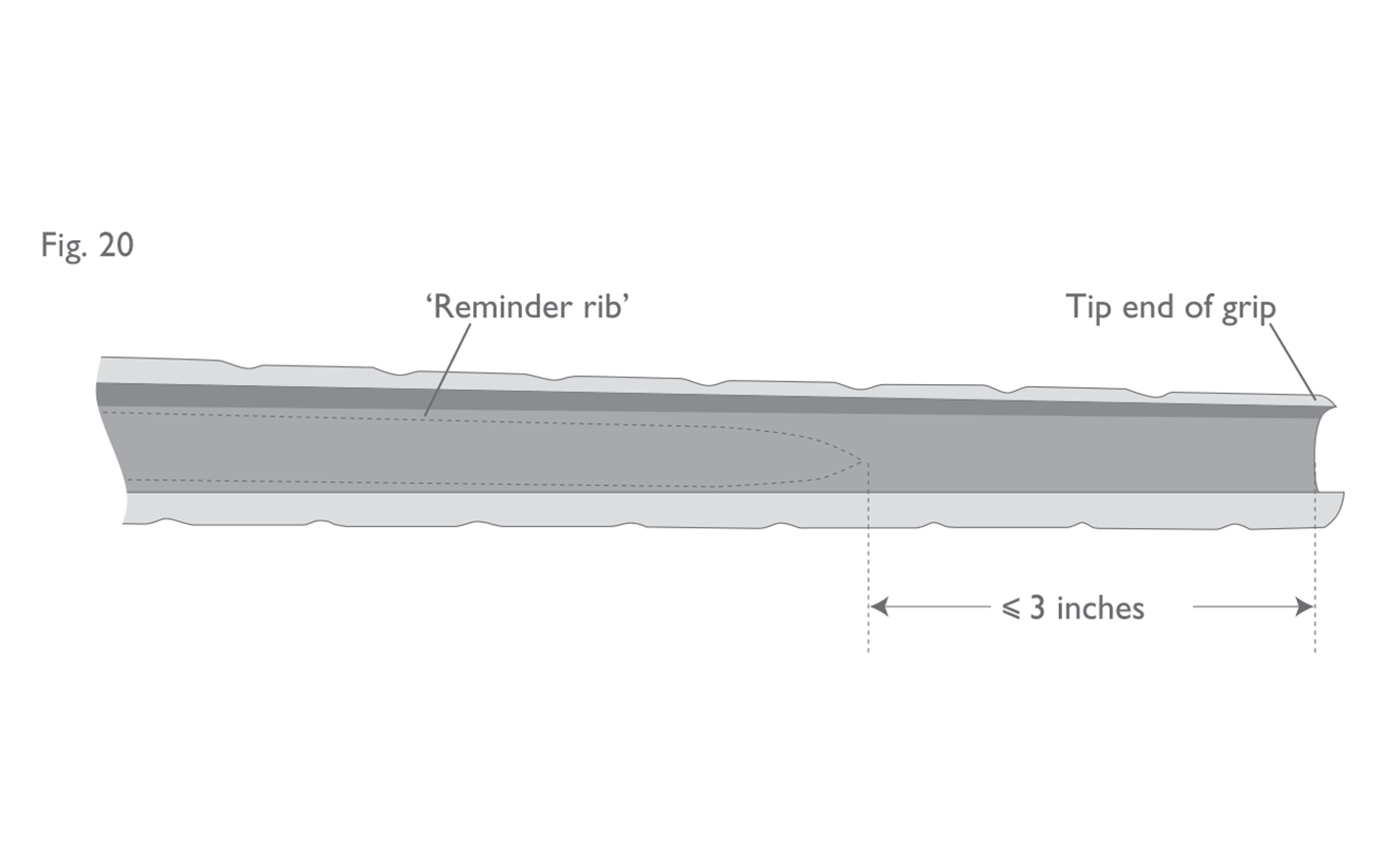
“Slightly raised” is interpreted to mean that the maximum and minimum diameters of the cross-section at any point must not differ by more than 0.040 inches (1.016 mm). While this measurement can be taken using a pair of callipers, due to the nature of gripping materials, the results of these measurements should be interpreted with caution in the field. An additional requirement, mainly for the benefit of manufacturers, is that the dimension of the rib width, from edge to edge, should not exceed 50% of the grip’s internal diameter. In the case of a standard length grip (approximately 10 inches (254 mm) in length), the “full length of the grip” is interpreted to mean that the rib must extend to within 3 inches (76.2 mm) of the tip (see Figure 20). This should generally be enough to cover the span of the player’s hands on the grip. Simulated leather wrapped grips moulded out of a rubber-like material with an indented spiral or other similar indentations are considered to be circular in cross-section and are permitted, as long as the fingers cannot comfortably fit in between the spirals or indentations. Similarly, features such as lines, dots or other patterned indentations, which are too small to fit even the smallest of fingers, would not of themselves render a grip non-circular in cross-section. However, any feature which is considered wide and deep enough to accommodate a finger or fingers could be ruled “moulded for the hands” and, hence, non-conforming. (ii) Putters As clearly stated in this clause, a putter grip may have a non‑circular cross-section, provided that, among other things, the cross-section remains generally similar throughout the length of the grip. In order to accommodate the popular (and somewhat traditional) “pistol-type” putter grips and also limit the amount of potential offset, the phrase “generally similar” is interpreted to mean: (i) that the butt (top) end of the grip must not involve a sharp change in slope or dramatic flare on the underside (see Figures 21(a) and (b)); (ii) that the flat front must extend to within 1 inch (25.4 mm) of the top and bottom ends (see Figure 21(c)); and (iii) if the axis of the grip and the shaft do not coincide, the grip must be at least 10 inches (254 mm) in length. As with circular grips, features such as lines, dots, or other patterned indentations, which are too small to fit even the smallest of fingers, would not of themselves render a putter grip not “generally similar throughout the length of the grip” or “moulded for the hands”.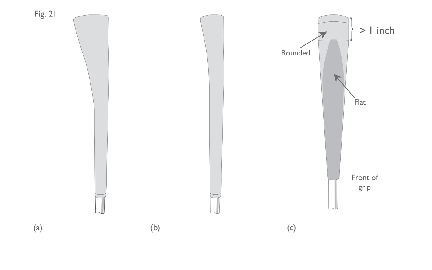
(iii) Cross-sectional Dimension This clause is self explanatory, though it is important to note that the measurement may be made in any direction on the horizontal plane, including diagonally. (iv) Axis of the Grip This clause requires that the axis of the circular grip on an iron or wood club coincides with the axis of the shaft. Therefore, a circular grip with the maximum diameter of 1.75 inches (44.45 mm) must not be mounted onto the shaft either off-centre or at an angle.
Fig 19: Grip cross-section and taper
Fig 20: End of raised rib in relation to tip end of grip
View from inside the grip
“Slightly raised” is interpreted to mean that the maximum and minimum diameters of the cross-section at any point must not differ by more than 0.040 inches (1.016 mm). While this measurement can be taken using a pair of callipers, due to the nature of gripping materials, the results of these measurements should be interpreted with caution in the field. An additional requirement, mainly for the benefit of manufacturers, is that the dimension of the rib width, from edge to edge, should not exceed 50% of the grip’s internal diameter. In the case of a standard length grip (approximately 10 inches (254 mm) in length), the “full length of the grip” is interpreted to mean that the rib must extend to within 3 inches (76.2 mm) of the tip (see Figure 20). This should generally be enough to cover the span of the player’s hands on the grip. Simulated leather wrapped grips moulded out of a rubber-like material with an indented spiral or other similar indentations are considered to be circular in cross-section and are permitted, as long as the fingers cannot comfortably fit in between the spirals or indentations. Similarly, features such as lines, dots or other patterned indentations, which are too small to fit even the smallest of fingers, would not of themselves render a grip non-circular in cross-section. However, any feature which is considered wide and deep enough to accommodate a finger or fingers could be ruled “moulded for the hands” and, hence, non-conforming. (ii) Putters As clearly stated in this clause, a putter grip may have a non‑circular cross-section, provided that, among other things, the cross-section remains generally similar throughout the length of the grip. In order to accommodate the popular (and somewhat traditional) “pistol-type” putter grips and also limit the amount of potential offset, the phrase “generally similar” is interpreted to mean: (i) that the butt (top) end of the grip must not involve a sharp change in slope or dramatic flare on the underside (see Figures 21(a) and (b)); (ii) that the flat front must extend to within 1 inch (25.4 mm) of the top and bottom ends (see Figure 21(c)); and (iii) if the axis of the grip and the shaft do not coincide, the grip must be at least 10 inches (254 mm) in length. As with circular grips, features such as lines, dots, or other patterned indentations, which are too small to fit even the smallest of fingers, would not of themselves render a putter grip not “generally similar throughout the length of the grip” or “moulded for the hands”.
Fig 21: Putter grip shape
(a) Non-conforming pistol grip, i.e. the flare is too dramatic. (b) Conforming pistol grip. Flat front is continuous throughout the length. The flare is not considered to be too dramatic. (c) Non-conforming pistol grip. The flat front does not extend to within an inch of the top.
(iii) Cross-sectional Dimension This clause is self explanatory, though it is important to note that the measurement may be made in any direction on the horizontal plane, including diagonally. (iv) Axis of the Grip This clause requires that the axis of the circular grip on an iron or wood club coincides with the axis of the shaft. Therefore, a circular grip with the maximum diameter of 1.75 inches (44.45 mm) must not be mounted onto the shaft either off-centre or at an angle.
2.3c
Two Grips
A putter may have two grips provided each is circular in cross-section, the axis of each coincides with the axis of the shaft, and they are separated by at least 1.5 inches (38.1 mm).
If a putter were allowed to have two non-circular grips, it would be possible to mount the grips such that their cross-section would not be “generally similar” throughout the entire length (see Section 3b above). For this reason, putters which have two grips must have two circular grips and this is interpreted strictly such that the grips must not incorporate a reminder rib.
Where a putter has two grips, these grips are only considered separate if the gap between them is at least 1.5 inches (38.1 mm) in length. If a smaller gap exists, or if no gap exists, the total length from the bottom of the lower grip to the top of the upper one would be considered “one grip”. Therefore, it is unlikely that the grip would conform if two conventional circular grips were installed without the required gap. Either the exposed piece of shaft between the two grips would constitute a waist, or the point where the two grips meet in the middle would cause a bulge. If there was no gap between the upper and lower grip, the grip could conform if the lower grip is a continuation of the upper grip, i.e. a continuation of the same taper, and the transition between the two sections is smooth (see Figure 22(d)).
If a putter does have two separated grips, the upper grip must be at least 5 inches (127 mm) in length. If the grip does not satisfy this requirement, it would be considered to be “moulded for the hands”.
Note: It is worth emphasising that it is not permissible for wood or iron clubs to have more than one grip.
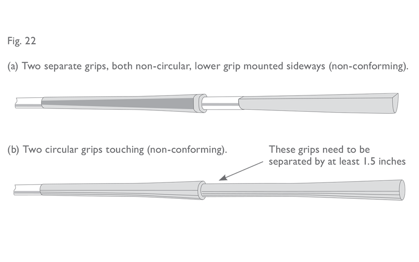
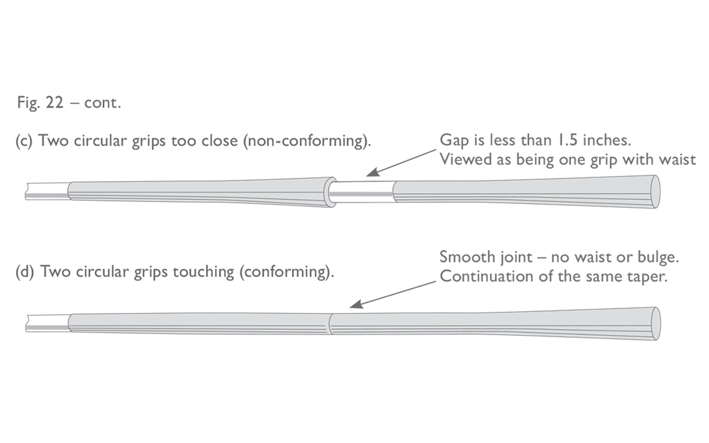
Fig 22 a b: Two grips on putters
Fig 22 c d: Two grips on putters
2.4
Clubhead
2.4a
Plain in Shape
The “plain in shape” requirement originates from the ‘traditional and customary’ requirement in Section 1a. It is purely a descriptive provision, although in reality it can be challenging to define exactly what a golf club can or should look like. The following sections assists in explaining and illustrating what is and what is not permitted, but it should be noted that the examples that follow are not all-inclusive. Additionally, even if a clubhead satisfies all of the points outlined below, there may still be features or characteristics which render it not generally plain in shape. An overall assessment of the appearance of the head should always be made.
The essence of Section 4a is encapsulated in the first three sentences of the general provision:
The clubhead must be generally plain in shape. All parts must be rigid, structural in nature and functional. The clubhead or its parts must not be designed to resemble any other object.
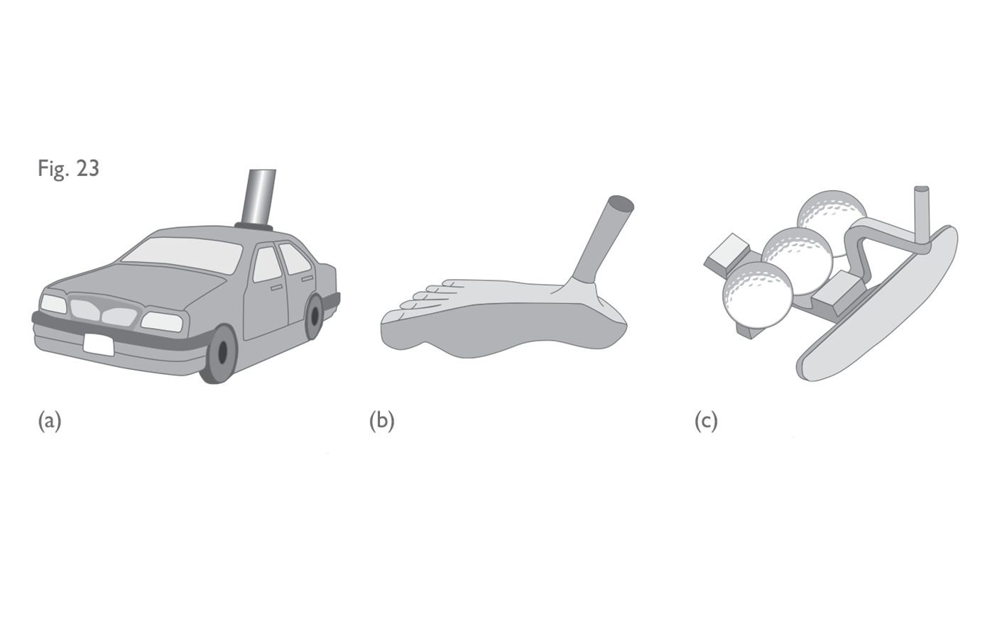
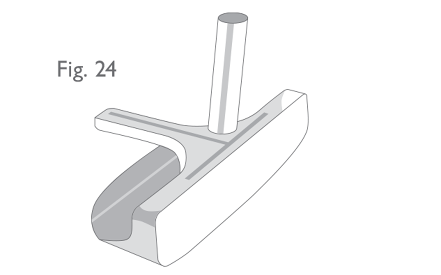
This provision basically means that the design of the clubhead must be free from gimmicks (though putters are viewed more liberally than woods and irons), must have the general appearance of a golf clubhead as opposed to another object and must not incorporate features which are designed to resemble another object (see Figure 23). All parts of the head (including permanent, permissible appendages) must be rigid throughout their length. As a general guideline, “rigid” means that it must not be possible to bend or flex the head or its parts by hand (see Figure 24).
 The general provision of Section 4a continues to state:
It is not practicable to define plain in shape precisely and comprehensively. However, features that are deemed to be in breach of this requirement and are therefore not permitted include, but are not limited to:
The above statement acknowledges that defining whether a clubhead is “plain in shape” is subjective. To better clarify the provision and its interpretation, it is split into two categories – one which covers “all clubs” and the other which covers the additional specifications relevant only to “irons and woods” The Section also reflects the more liberalized application for putters which has evolved over the years and provides more detail regarding what is and what is not permitted for iron heads and woodheads. Following are general guidelines and illustrations for the two categories of “plain in shape”:
(i) All Clubs
• holes through the face;
• holes through the head (some exceptions may be made for putters and cavity back irons);
• features that are for the purpose of meeting dimensional specifications;
• features that extend into or ahead of the face;
• features that extend significantly above the top line of the head;
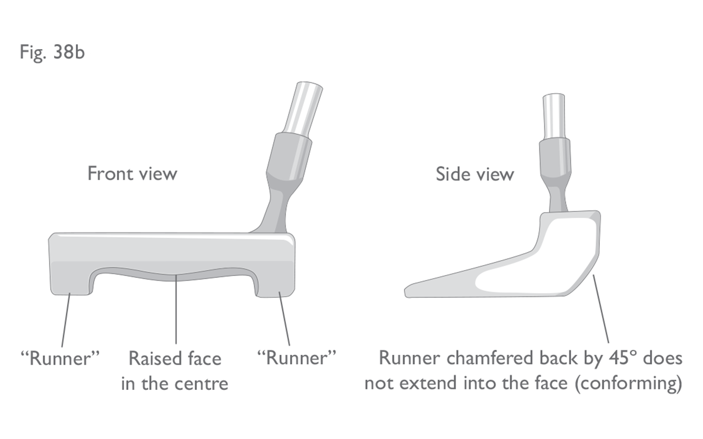
• furrows in or runners on the head that extend into the face (some exceptions may be made for putters); and
• optical or electronic devices.
To take each of these clauses in turn:
Holes through the Face
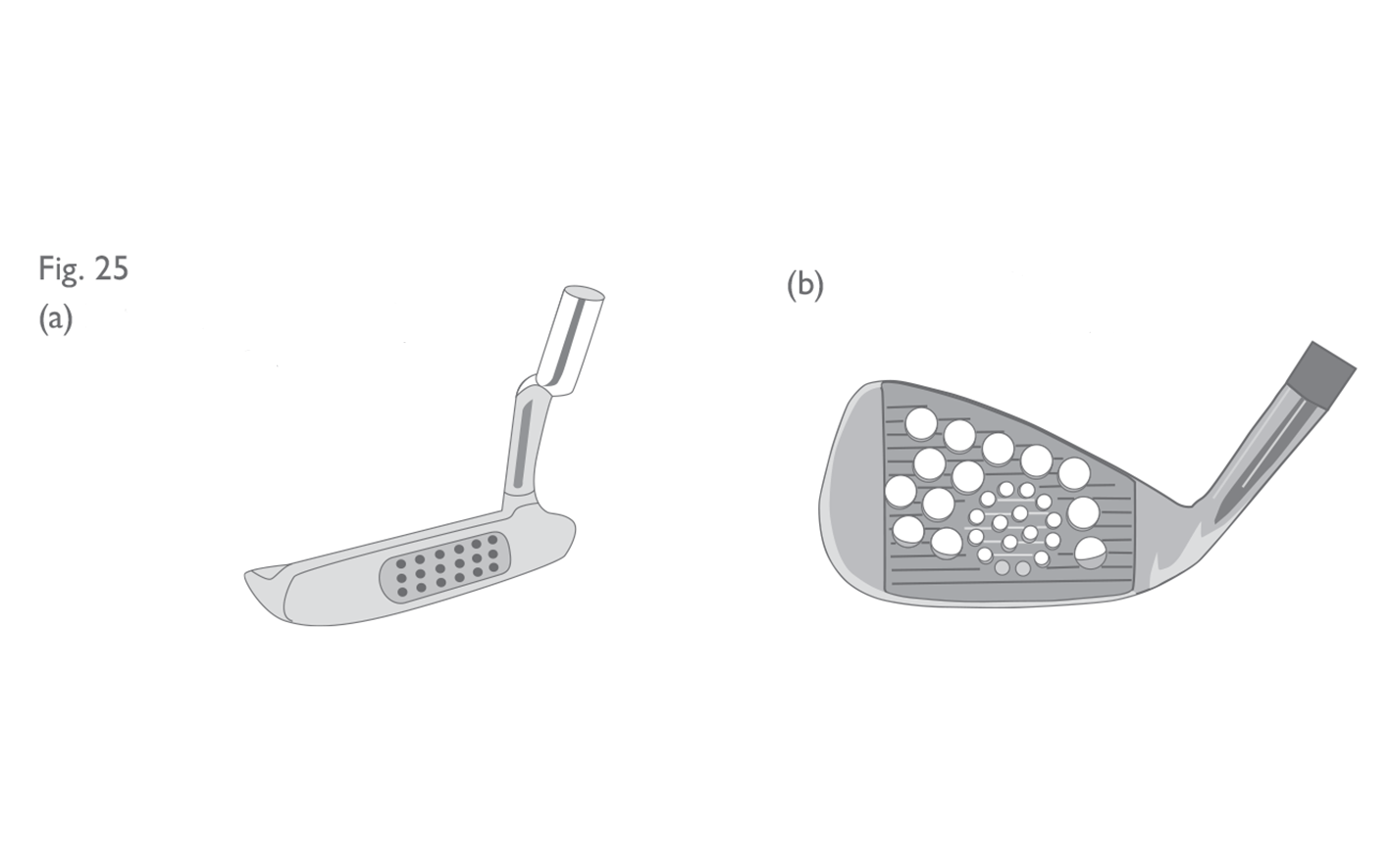
Holes through the face are not permitted – see Figure 25.
The general provision of Section 4a continues to state:
It is not practicable to define plain in shape precisely and comprehensively. However, features that are deemed to be in breach of this requirement and are therefore not permitted include, but are not limited to:
The above statement acknowledges that defining whether a clubhead is “plain in shape” is subjective. To better clarify the provision and its interpretation, it is split into two categories – one which covers “all clubs” and the other which covers the additional specifications relevant only to “irons and woods” The Section also reflects the more liberalized application for putters which has evolved over the years and provides more detail regarding what is and what is not permitted for iron heads and woodheads. Following are general guidelines and illustrations for the two categories of “plain in shape”:
(i) All Clubs
• holes through the face;
• holes through the head (some exceptions may be made for putters and cavity back irons);
• features that are for the purpose of meeting dimensional specifications;
• features that extend into or ahead of the face;
• features that extend significantly above the top line of the head;
• furrows in or runners on the head that extend into the face (some exceptions may be made for putters); and
• optical or electronic devices.
To take each of these clauses in turn:
Holes through the Face
Holes through the face are not permitted – see Figure 25.
 Holes through the Head

 Features for the purpose of meeting Dimensional Specifications
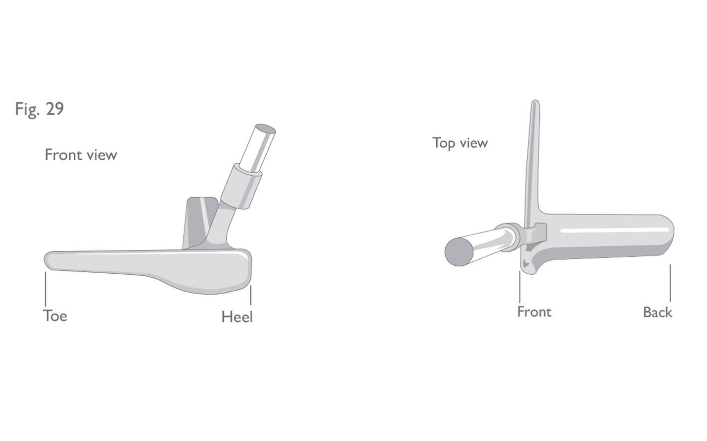
For all clubs, the distance from the heel to the toe of the clubhead must be greater than the distance from the front to the back (see Section 4b, below). Clubs which incorporate features which are designed to or have the effect of circumventing this requirement are not permitted – see Figure 29.
Features for the purpose of meeting Dimensional Specifications
For all clubs, the distance from the heel to the toe of the clubhead must be greater than the distance from the front to the back (see Section 4b, below). Clubs which incorporate features which are designed to or have the effect of circumventing this requirement are not permitted – see Figure 29.
 Features that extend into or ahead of the face
 Features above the top line of the head
 Furrows and/or runners are deemed to extend into the face if the leading edge of the face has any concavity (point of inflection or turning point).
The application of this provision is fairly straightforward in most cases and can be determined simply by placing a straight edge along the leading edge of the face and looking to see if there is a gap between these two edges. However, woods and hybrids commonly have a smooth transition between the face and the rest of the body which can sometimes make it difficult to determine, in a repeatable and reproducible manner, whether features “extend into” or intersect the face.
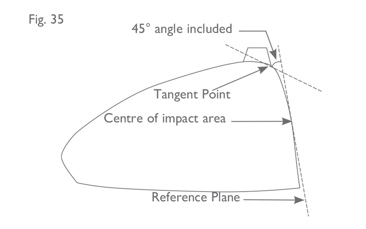
Where the transition between the body and the face is not clearly defined, i.e. the face does not meet the body at a sharp edge or chamfer, the point of intersection shall be defined as the point where a line inclined at 45° from the reference plane is tangent to the cross-section (see Figure 35).
Furrows and/or runners are deemed to extend into the face if the leading edge of the face has any concavity (point of inflection or turning point).
The application of this provision is fairly straightforward in most cases and can be determined simply by placing a straight edge along the leading edge of the face and looking to see if there is a gap between these two edges. However, woods and hybrids commonly have a smooth transition between the face and the rest of the body which can sometimes make it difficult to determine, in a repeatable and reproducible manner, whether features “extend into” or intersect the face.
Where the transition between the body and the face is not clearly defined, i.e. the face does not meet the body at a sharp edge or chamfer, the point of intersection shall be defined as the point where a line inclined at 45° from the reference plane is tangent to the cross-section (see Figure 35).
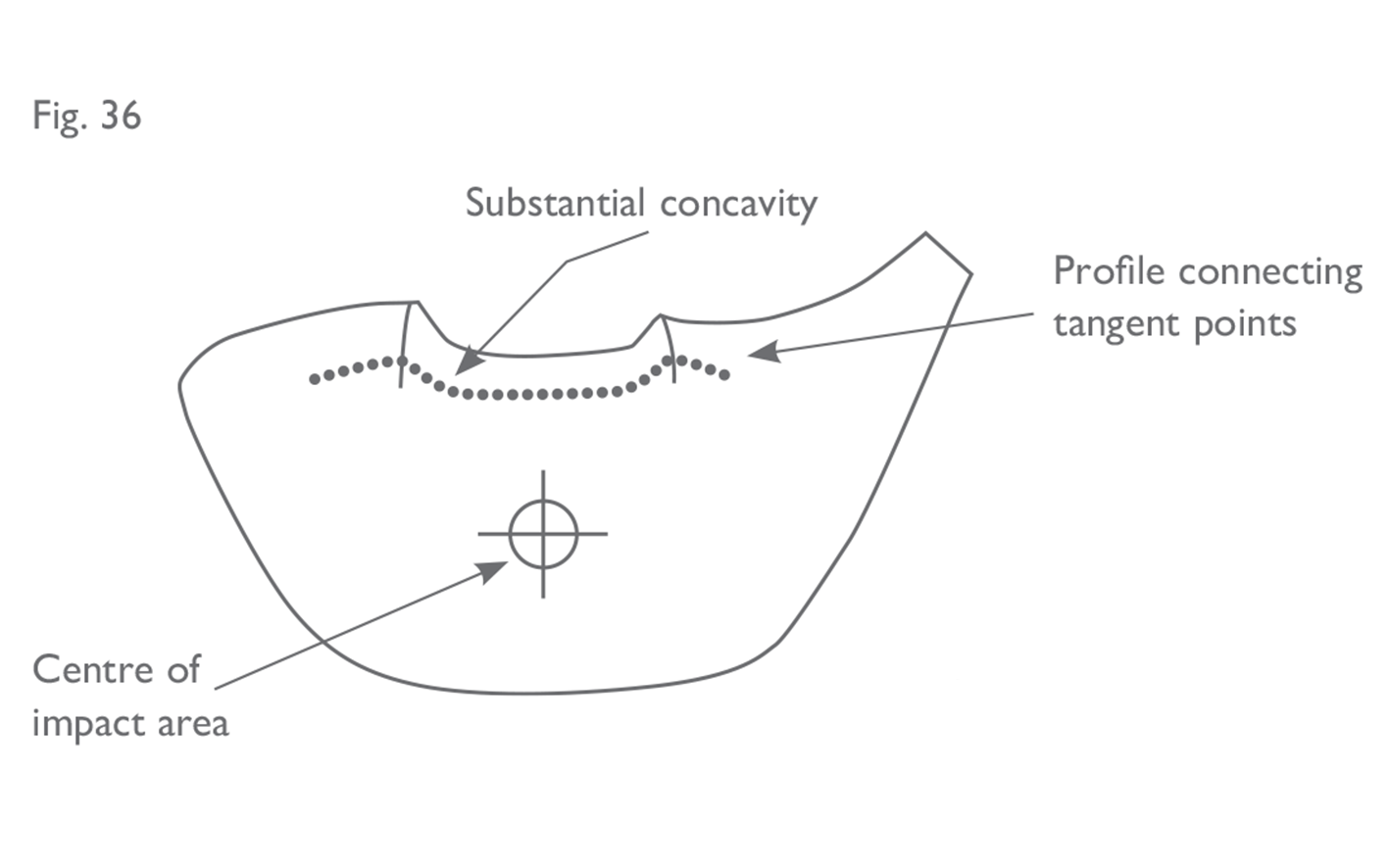 Any substantial concavities in said profile are considered sufficient evidence that a runner or furrow extends into the face and thus does not conform with Section 4a(i).
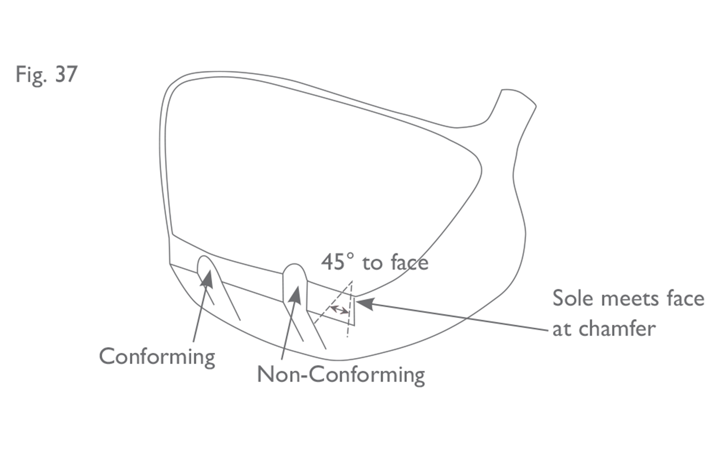
Where the transition between the body and face is clearly defined by a chamfer of at least 45° with respect to the face, furrows and/or runners are permitted to intersect the chamfered surface, provided the feature does not intersect the face itself (see Figure 37).
Any substantial concavities in said profile are considered sufficient evidence that a runner or furrow extends into the face and thus does not conform with Section 4a(i).
Where the transition between the body and face is clearly defined by a chamfer of at least 45° with respect to the face, furrows and/or runners are permitted to intersect the chamfered surface, provided the feature does not intersect the face itself (see Figure 37).
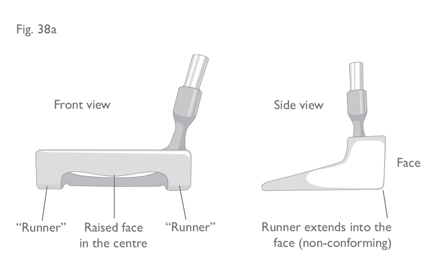
 If a runner has been chamfered back away from the face, by at least 45°, then it would not be considered to extend into the face – see Figure 38.
 Optical and Electrical Devices
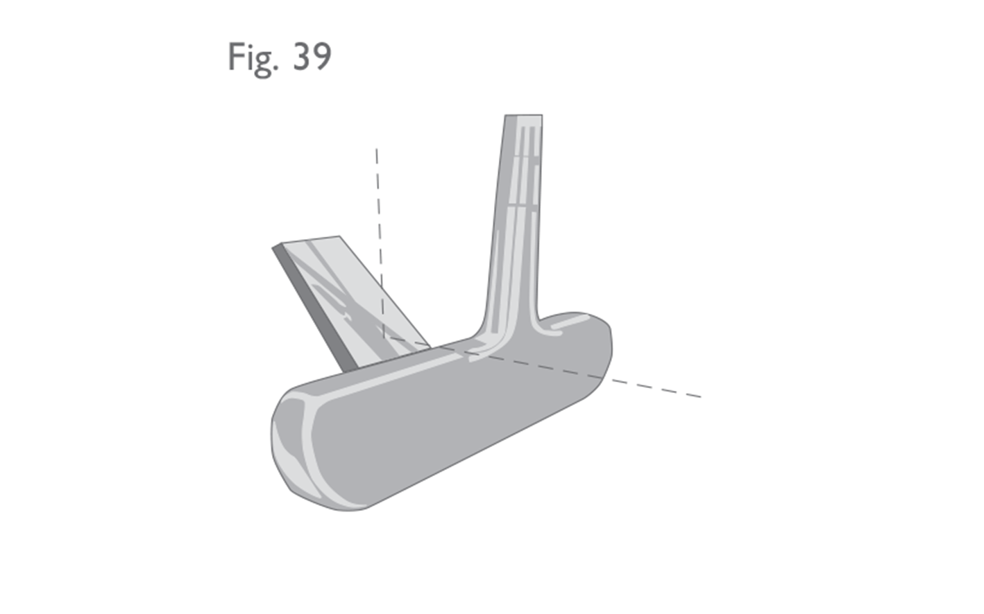
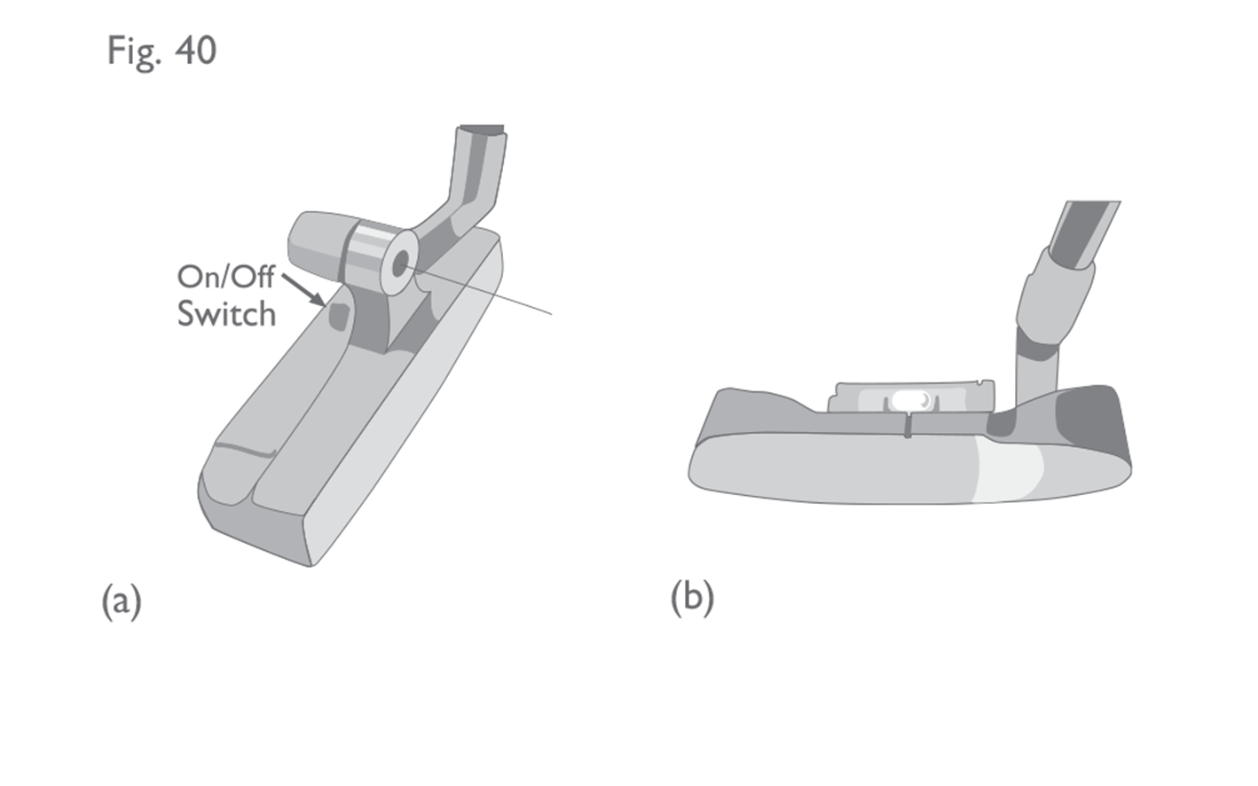
Clubheads which incorporate prisms, mirrors, reflective materials, light beams, metronomes or mechanical devices such as spirit levels are not permitted – see Figures 39 and 40.
Optical and Electrical Devices
Clubheads which incorporate prisms, mirrors, reflective materials, light beams, metronomes or mechanical devices such as spirit levels are not permitted – see Figures 39 and 40.
 Electronic devices in or on the club shaft or grip, which have the sole purpose of identifying the club, may be permitted. The identification information is restricted to:
(a) the club’s owner, such as address and phone number;
(b) inventory tracking information;
(c) detection of the club’s use during a round.
Any such device must meet all other requirements of the Equipment Rules and must not vibrate or emit light or sound. If the device is capable of any function other than identification, the golf club will be considered not traditional and customary in form and make (see Section 1a (i)) and, therefore, non-conforming.
Note: Any device or application used in conjunction with a club incorporating such a device must comply with the provisions of Rule 4.3 of the Rules of Golf.
In addition to the provisions above, the “plain in shape” guidelines and illustrations for woods and irons are:
(ii) Woods and Irons
• all features listed in (i) above;
• cavities in the outline of the heel and/or the toe of the head that can be viewed from above;
• severe or multiple cavities in the outline of the back of the head that can be viewed from above;
• transparent material added to the head with the intention of rendering conforming a feature that is not otherwise permitted; and
• features that extend beyond the outline of the head when viewed from above.
In essence, the purpose of these additional requirements is to help preserve the traditional shape and appearance of such clubheads when viewed from above. The “plain in shape” provisions for woods and irons are less focused on sole features or other features which cannot be viewed from above. To go through each of these provisions in turn:
Cavities in the Outline of the Heel and/or Toe
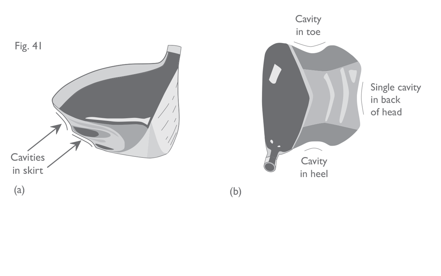
When making this assessment, “viewed from above” is interpreted to mean the range from directly above the head to the normal address position for that club. The restriction does not apply to horizontal cavities around the skirt of the head, which might be visible from above – see Figures 41a and b.
Electronic devices in or on the club shaft or grip, which have the sole purpose of identifying the club, may be permitted. The identification information is restricted to:
(a) the club’s owner, such as address and phone number;
(b) inventory tracking information;
(c) detection of the club’s use during a round.
Any such device must meet all other requirements of the Equipment Rules and must not vibrate or emit light or sound. If the device is capable of any function other than identification, the golf club will be considered not traditional and customary in form and make (see Section 1a (i)) and, therefore, non-conforming.
Note: Any device or application used in conjunction with a club incorporating such a device must comply with the provisions of Rule 4.3 of the Rules of Golf.
In addition to the provisions above, the “plain in shape” guidelines and illustrations for woods and irons are:
(ii) Woods and Irons
• all features listed in (i) above;
• cavities in the outline of the heel and/or the toe of the head that can be viewed from above;
• severe or multiple cavities in the outline of the back of the head that can be viewed from above;
• transparent material added to the head with the intention of rendering conforming a feature that is not otherwise permitted; and
• features that extend beyond the outline of the head when viewed from above.
In essence, the purpose of these additional requirements is to help preserve the traditional shape and appearance of such clubheads when viewed from above. The “plain in shape” provisions for woods and irons are less focused on sole features or other features which cannot be viewed from above. To go through each of these provisions in turn:
Cavities in the Outline of the Heel and/or Toe
When making this assessment, “viewed from above” is interpreted to mean the range from directly above the head to the normal address position for that club. The restriction does not apply to horizontal cavities around the skirt of the head, which might be visible from above – see Figures 41a and b.
 Severe or Multiple Cavities in the Outline of the Back of the Head
 Transparent Material
Fig 23 a b c: Facsimiles of other objects
(a) Putter head in the shape of a car (non-conforming). (b) Putter head in the shape of a foot (non-conforming). (c) Putter head incorporating three facsimiles of a golf ball (non-conforming).
Fig 24: Putter with appendage
Putter with appendage for aiming/accommodating a sighting line. As long as the appendage is rigid, putter is conforming.
Fig 25 a b: Holes through the face
(a) Putter with holes in the face insert (non-conforming). (b) Iron head with holes through the face (non-conforming).
- Holes through the head are not permitted for wood heads – see Figure 26.
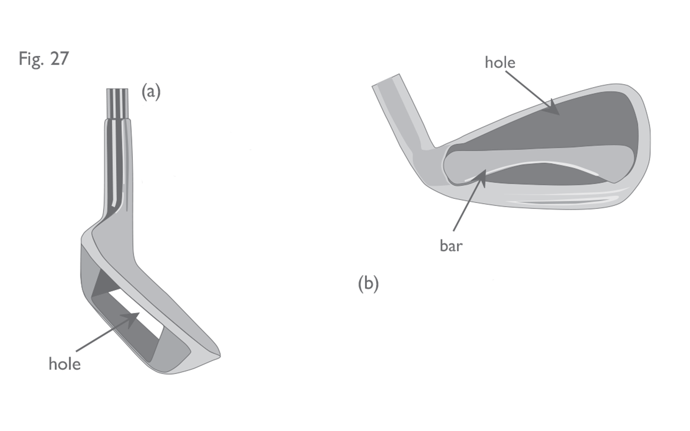
- Holes through the head are not permitted for iron heads. However, features within the cavity back of an iron clubhead that form a hole or holes may be permitted, (e.g. support bars), provided that the feature is contained within the outline of the main body of the head and the hole cannot be viewed from above – see Figure 27 a/b.
Fig 26: Hole through the head (woods)
Wood head with hole from crown to sole (non-conforming).
Fig 27 a b: Hole through the head (irons)
(a) Sand wedge with hole through the head designed to help head cut through the sand (non-conforming). (b) The bar across the cavity back of this iron head creates a hole, but the feature is contained within the outline of the main body of the head (conforming).
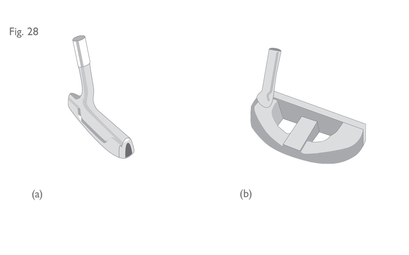
- This provision is interpreted very liberally for putters and holes through the head (excluding the face) for any purpose including aiming, sighting or alignment are permitted – see Figure 28 for examples of permissible holes through the head of a putter.
Fig 28 a b: Holes through the head (putters)
(a) Putter with hole extending from toe to hell (conforming). (b) Putter with vertical holes from top to bottom (conforming).
Fig 29: Features for meeting dimensional specifications
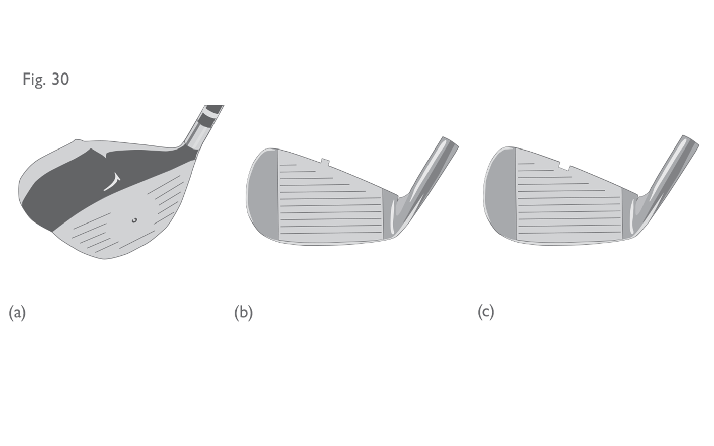
- Permitted features in or on the main body of the head must not extend into the face of an iron or wood club. This would include alignment features on the crown – see Figure 30. Alignment lines which have been engraved or inscribed onto an iron clubhead would generally be permitted.
Fig 30 a b c: Features extending into the face
(a) Raised alignment feature on crown of head, which does not extend into the face (conforming). (b) Iron head with raised alignment feature on the crown which extends into the face (non-conforming). (c) Iron head with indented alignment feature on the crown which extends into the face (non-conforming).
- Certain features are permitted to extend into the face of a putter, including alignment features and concavities (or furrows) on the crown (see Section below on Furrows and Runners). However, such features must not have a depth or height greater than 0.25 inches (6.35 mm) when measured against the top line of the face.
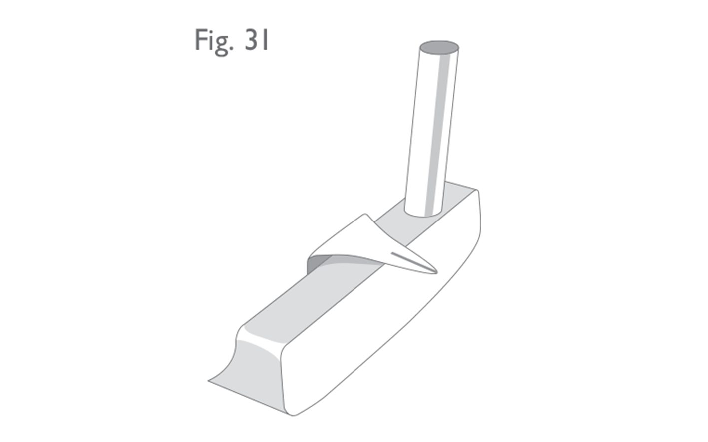
- Features of any nature that extend ahead of the face are not permitted on any club – see Figure 31.
Fig 31: Features extending ahead of the face
Putter with projection ahead of the face for aiming (non-conforming).
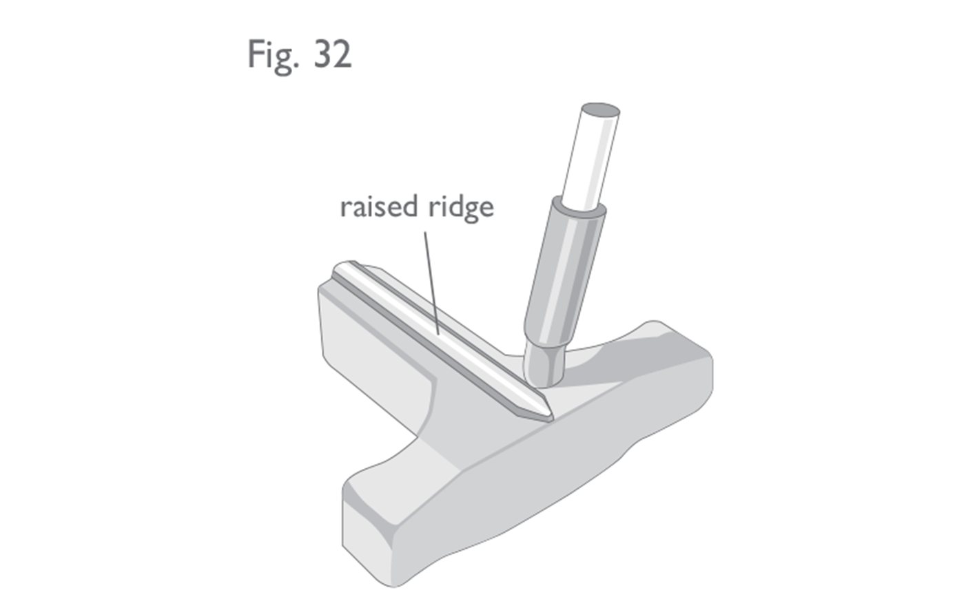
Fig 32: Features above the top line of the head (putters)
The alignment feature or ridge which extends above the top line of this face of this putter is less than 0.25 inches (6.35 mm) in depth. Therefore, putter is conforming.
- For putters, alignment or other features must not extend above the top line of the face by more than 0.25 inches (6.35 mm) – see Figure 32.
- For woods and irons, features which otherwise meet the requirements for “plain in shape” must not extend above the top line of the head by more than 0.1 inch (2.54 mm).
- Permanent or semi-permanent lines or other markings which have been painted, inscribed or otherwise incorporated (see Section 1a) for alignment purposes are permitted.
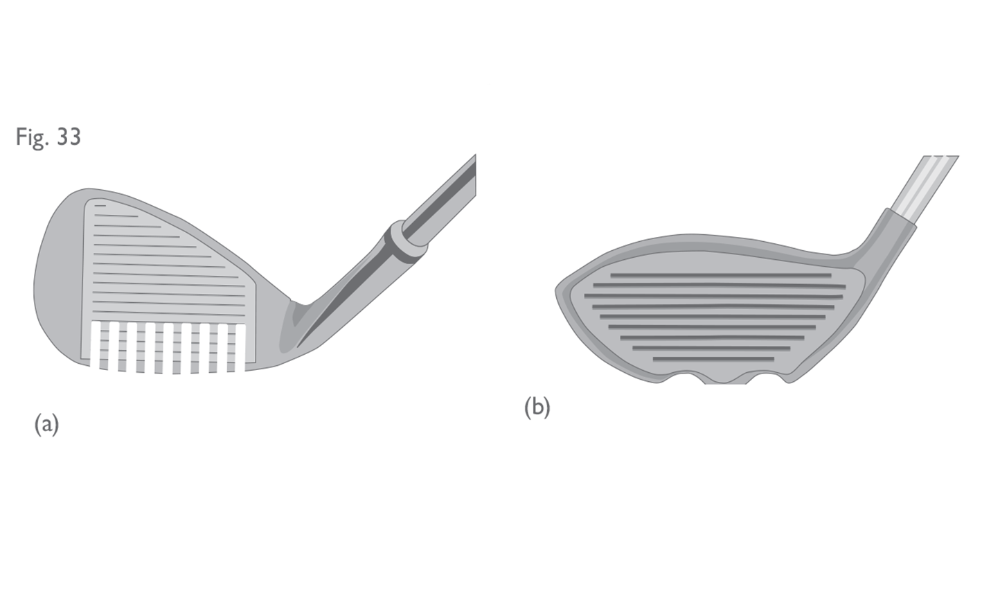
- Furrows or runners which extend into the face of a wood or iron club from any part of the head are not permitted – see Figure 33.
Fig 33 a b: Furrows and runners
(a) Iron head with rake-like furrows in the sole - which extend into the face (non-conforming). (b) Wood head with runners which extend into the face (non-conforming).
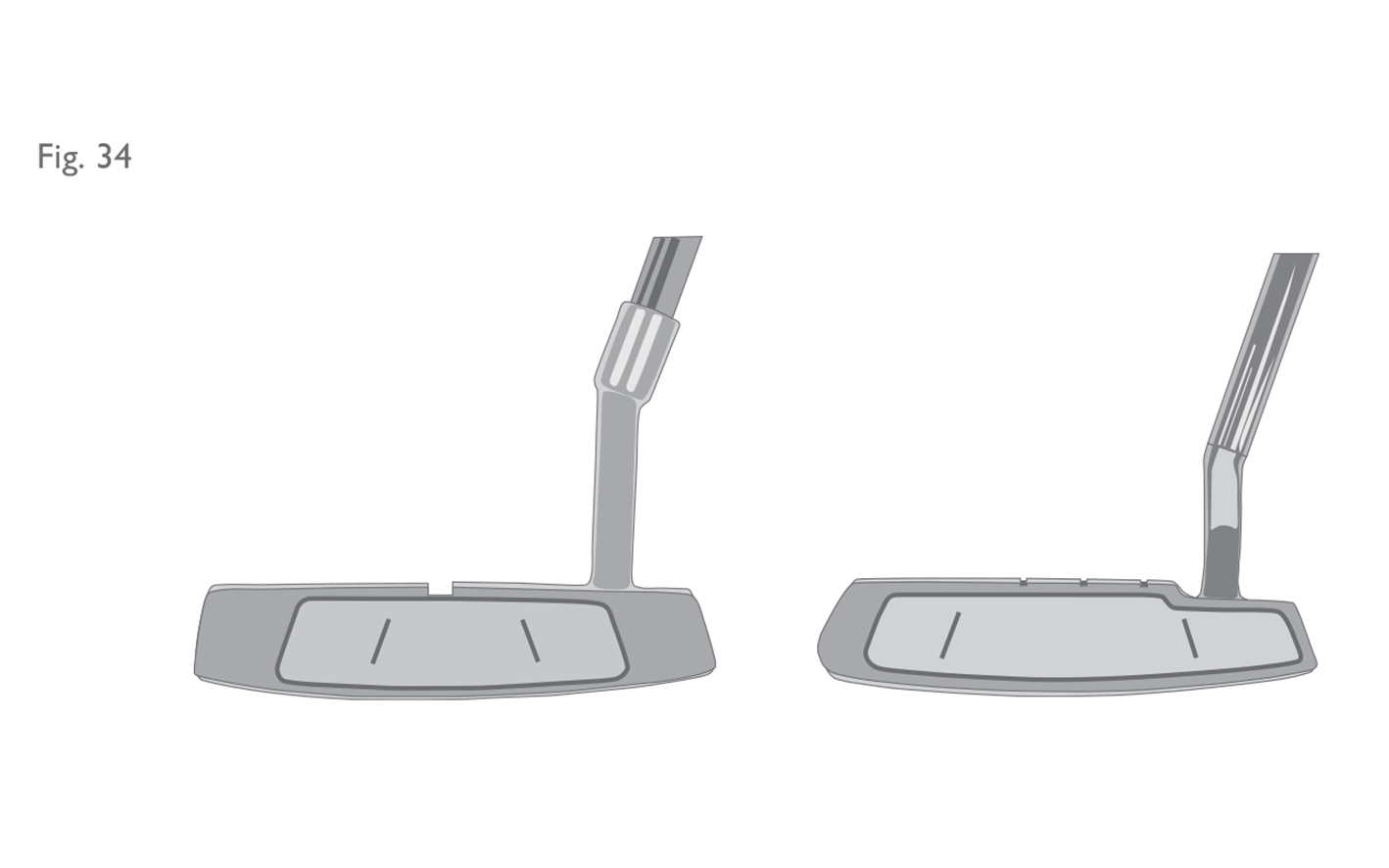
- While this provision is applied strictly for furrows or runners which may appear on the sole of a putter, exceptions may be made for other parts of the head – see Figure 34.
Fig 34: Furrows and runners - exceptions for putters
Examples of putters with features on the top/crown of the head which extend into the face. These are permitted as long as they do not have a depth greater than 0.25 inches (6.35 mm).
Fig 35: Definition of intersection between face and body
Example clubhead illustrating a tangent point defining the intersection between the face and body.
- A reference plane is defined as the plane tangent to the face at the centre of the impact area.
- A vertical cross-section is created by establishing a plane perpendicular to the reference plane, usually running through the centre of the face/clubhead and the area of interest (i.e. furrow or runner).
Fig 36: Profile of intersection between face and body
Profile generated by connecting tangent points identified using the method illustrated in Figure 35. The club in this figure is non-conforming due to the substantial concavity.
Fig 37: Furrows - examples of conforming and non-conforming
Conforming and non-conforming furrows, where the transition between the face and the body of the clubhead is defined by a chamfer of angle not less than 45°.
Fig 38 a: Putter with runners at the heel and toe (non-conforming)
Fig 38 b: Putter with runners at heel and toe (conforming)
Putter with chamfered runners at the heel and toe.
Fig 39: Optical devices
Putter head with sighting mirror attached to the back of the head at 45° angle to view target (non-conforming).
Fig 40 a b: Electrical and mechanical devices
(a) Putter with laser beam sighting mechanism built into the head (non-conforming). (b) Putter with spirit level at the back of the head (non-conforming).
Fig 41 a b: Cavities in head
(a) Wood head with cavities in the 'skirt' or sides of the head (conforming). (b) Wood head with cavity in outline of the toe and the heel which can be viewed at address (non-conforming). The single cavity at the back of the head is not 'severe' and, therefore, is permitted.
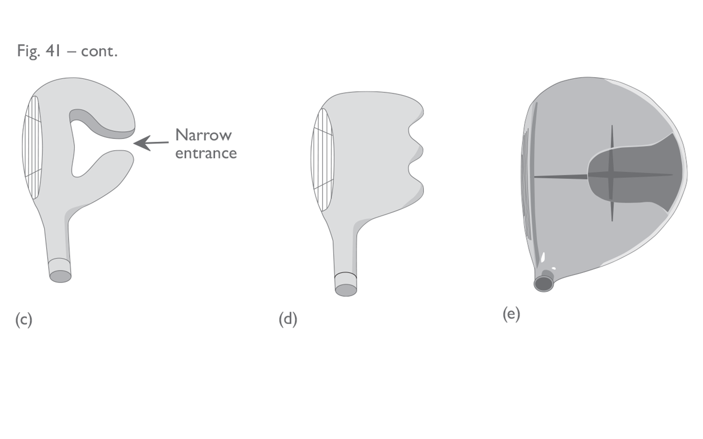
- Severe cavities (as viewed at address), which go all the way through the head, are not permitted. A “severe” cavity is one where the entrance to the cavity is narrower than its width at any other point – see Figure 41c.
- A single cavity in the back of the head is permitted – see Figure 41b. However, multiple cavities are not permitted – see Figure 41d.
- Cavities in the crown of the head are permitted, even if they are designed primarily as an aid to sighting, aiming or aligning the swing plane or the head position, or to accommodate markings for such aids – see Figure 41e. However, all cavities on the crown are filled for the purpose of measuring the volume of the head – see Section 4b(i)).
Fig 41 c d e: Cavities in head (cont)
(c) Wood head with 'severe' concavity (non-conforming). (d) Wood head with multiple cavities in outline of back of head (non-conforming). (e) Wood head with cavity in crown of head (conforming - with or without sighting lines).
- Clubheads made entirely of transparent material are permitted.
- Transparent material that is added to an otherwise non-plain head does not render the head “plain in shape”. For example, a wood head which has a vertical hole from the top surface through to the sole would be ruled non-conforming (see Section 4a(i) and Figure 26). Filling this hole with a transparent material (e.g. perspex or glass), would not alter this ruling.
- the feature is rigid throughout its length (i.e., cannot be bent or flexed by hand);
- the feature does not extend forward of the face; and,
- the features does not extend above the top line of the face by more than 0.25 inches (6.35 mm).
2.4b
Dimensions, Volume and Moment of Inertia
Section 4b is divided into three categories – woods, irons and putters. The volume and moment of inertia limits apply only to woodheads.
(i) Woods
Dimensional specifications:
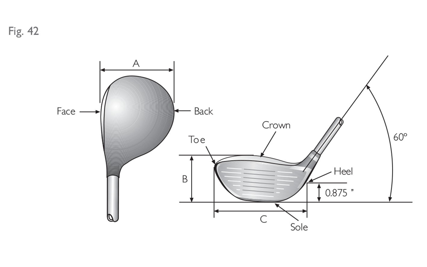
When the club is in a 60 degree lie angle, the dimensions of the clubhead must be such that:
• the distance from the heel to the toe of the clubhead is greater than the distance from the face to the back;
• the distance from the heel to the toe of the clubhead is not greater than 5 inches (127 mm); and
• the distance from the sole to the crown of the clubhead, including any permitted features, is not greater than 2.8 inches (71.12 mm).
These dimensions are measured on horizontal lines between vertical projections of the outermost points of:
• the heel and the toe; and
• the face and the back (see Fig. 42, dimension A); and on vertical lines between the horizontal projections of the outermost points of the sole and the crown (see Fig. 42, dimension B). If the outermost point of the heel is not clearly defined, it is deemed to be 0.875 inches (22.23 mm) above the horizontal plane on which the club is lying (see Fig. 42, dimension C).
 When performing these measurements in the field, the best method would be to use a pair of callipers. For the heel to toe measurement, a rigid, straight edge (e.g. a ruler) should be held upright against the extremity of the toe end.
Volume limit:
The volume of the clubhead must not exceed 460 cubic centimetres (28.06 cubic inches), plus a tolerance of 10 cubic centimetres (0.61 cubic inches).
In practice, many of the larger headed clubheads in the market place have a marking somewhere on the head indicating the approximate volume of the head (this is the cubic centimetres or “cc” value).
Fortunately, for clubs where there is no indication of volume, there is a fairly simple method of determining the actual volume of a clubhead in the field and it is broadly based on Archimedes’ Principle and the displacement of water. All that is needed is a large measuring container, half filled with water. The measure of clubhead volume would be the amount by which the water level rises once the clubhead has been submerged into the water. Therefore, if the container is filled with 1 litre of water and the level rises to 1450 millilitres when the head is submerged to the base of the hosel – this would mean that the head has a volume of 450 cubic centimetres.
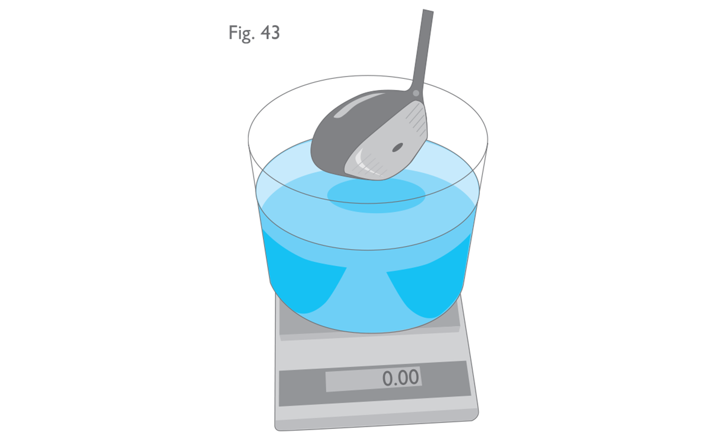
The official test protocol for measuring volume is a more accurate method, but not that much more complicated, and it requires a similar container of water placed on a set of digital weighing scales.
Archimedes’ Principle states that the buoyant force on a submerged object is equal to the weight of the fluid that is displaced by the object – and since water has a specific gravity of 1.0, this means that 1 cubic centimetre of water has a mass of 1 gram. Therefore, the container of water should be placed on the scales and the weight should be set to zero. When the head is submerged in the water, the weight displayed on the scales (in grams) is equivalent to the volume of the head (in cubic centimetres).
In situations where a club is marked with a “cc” value which is in excess of the Rule (i.e. above 460 cubic centimetres), The R&A’s and USGA’s policy is to rule that the club is non-conforming – regardless of the actual volume measurement. This is to avoid confusion in the marketplace.
Prior to measuring the volume of a clubhead, the head should be inspected for cavities. All cavities on the crown should be filled with waterproof clay or other similar material to create a ‘straight line’ which connects the edges of the cavity. The ‘straight line filling technique’ does not follow the taper or curvature of the surface of the head, rather the cavity is filled so that it becomes a flat surface which adjoins the outer edges.
Only significant concavities on the sole will be filled, meaning any cavity or series of cavities which have a collective volume of greater than 15 cc.
When performing these measurements in the field, the best method would be to use a pair of callipers. For the heel to toe measurement, a rigid, straight edge (e.g. a ruler) should be held upright against the extremity of the toe end.
Volume limit:
The volume of the clubhead must not exceed 460 cubic centimetres (28.06 cubic inches), plus a tolerance of 10 cubic centimetres (0.61 cubic inches).
In practice, many of the larger headed clubheads in the market place have a marking somewhere on the head indicating the approximate volume of the head (this is the cubic centimetres or “cc” value).
Fortunately, for clubs where there is no indication of volume, there is a fairly simple method of determining the actual volume of a clubhead in the field and it is broadly based on Archimedes’ Principle and the displacement of water. All that is needed is a large measuring container, half filled with water. The measure of clubhead volume would be the amount by which the water level rises once the clubhead has been submerged into the water. Therefore, if the container is filled with 1 litre of water and the level rises to 1450 millilitres when the head is submerged to the base of the hosel – this would mean that the head has a volume of 450 cubic centimetres.
The official test protocol for measuring volume is a more accurate method, but not that much more complicated, and it requires a similar container of water placed on a set of digital weighing scales.
Archimedes’ Principle states that the buoyant force on a submerged object is equal to the weight of the fluid that is displaced by the object – and since water has a specific gravity of 1.0, this means that 1 cubic centimetre of water has a mass of 1 gram. Therefore, the container of water should be placed on the scales and the weight should be set to zero. When the head is submerged in the water, the weight displayed on the scales (in grams) is equivalent to the volume of the head (in cubic centimetres).
In situations where a club is marked with a “cc” value which is in excess of the Rule (i.e. above 460 cubic centimetres), The R&A’s and USGA’s policy is to rule that the club is non-conforming – regardless of the actual volume measurement. This is to avoid confusion in the marketplace.
Prior to measuring the volume of a clubhead, the head should be inspected for cavities. All cavities on the crown should be filled with waterproof clay or other similar material to create a ‘straight line’ which connects the edges of the cavity. The ‘straight line filling technique’ does not follow the taper or curvature of the surface of the head, rather the cavity is filled so that it becomes a flat surface which adjoins the outer edges.
Only significant concavities on the sole will be filled, meaning any cavity or series of cavities which have a collective volume of greater than 15 cc.
 Moment of Inertia (MOI):
When the club is in a 60 degree lie angle, the moment of inertia component around the vertical axis through the clubhead’s centre of gravity must not exceed 5900 g cm2 (32.259 oz in2), plus a test tolerance of 100 g cm2 (0.547 oz in2).
The MOI test is a measurement of a clubhead’s resistance to twisting and, therefore, it is an indication of its ‘forgiveness’.
The measurement of MOI is one of the few limits within the Equipment Rules which cannot easily be performed in the field. This is because the testing equipment is very specialized and it can only be measured by de-shafting the head (the hosel remains on the head for the purpose of the test). However, high MOI is only associated with modern, hollow, high volume driver heads and, due to the publication of the List of Conforming Driver Heads (see Rule 4c below), most of these clubs are now routinely submitted to the Governing Bodies for a ruling – so that they can be included on this List.
As the MOI of a driver head is affected by a change in its weight and the position of the centre of gravity, a driver which is designed to be adjustable for weight must conform to the Equipment Rules in all configurations (see Rule 1b). Moreover, when adding additional weight to a driver (e.g. with lead tape), the player must be certain that the club is still within the limit. To assist golfers with this determination, The R&A and USGA have developed a policy whereby if a driver head is submitted for a ruling and it is measured to have an MOI which is close to the limit, the manufacturer will be encouraged to advise its customers that the addition of any other weights to that model (including lead tape), other than the weights which were supplied by the manufacturer, is not permitted as it would likely render the club non-conforming. Additionally, the manufacturer must take care over its claims and must not advertise that the product is over the limit for MOI.
(ii) Irons
When the clubhead is in its normal address position, the dimensions of the head must be such that the distance from the heel to the toe is greater than the distance from the face to the back.
In practice, due to the shape and size of iron heads, this provision is rarely encroached. It is retained in the Equipment Rules, in part, to help maintain the traditional shape by which irons are recognized. However, while most irons are still relatively narrow from front to back, the popularity of hybrid clubs means that this provision has greater utility today.
(iii) Putters (see Fig. 44)
When the clubhead is in its normal address position, the dimensions of the head must be such that:
• the distance from the heel to the toe is greater than the distance from the face to the back;
• the distance from the heel to the toe of the head is less than or equal to 7 inches (177.8 mm);
• the distance from the heel to the toe of the face is greater than or equal to two thirds of the distance from the face to the back of the head;
• the distance from the heel to the toe of the face is greater than or equal to half of the distance from the heel to the toe of the head; and
• the distance from the sole to the top of the head, including any permitted features, is less than or equal to 2.5 inches (63.5 mm).
Moment of Inertia (MOI):
When the club is in a 60 degree lie angle, the moment of inertia component around the vertical axis through the clubhead’s centre of gravity must not exceed 5900 g cm2 (32.259 oz in2), plus a test tolerance of 100 g cm2 (0.547 oz in2).
The MOI test is a measurement of a clubhead’s resistance to twisting and, therefore, it is an indication of its ‘forgiveness’.
The measurement of MOI is one of the few limits within the Equipment Rules which cannot easily be performed in the field. This is because the testing equipment is very specialized and it can only be measured by de-shafting the head (the hosel remains on the head for the purpose of the test). However, high MOI is only associated with modern, hollow, high volume driver heads and, due to the publication of the List of Conforming Driver Heads (see Rule 4c below), most of these clubs are now routinely submitted to the Governing Bodies for a ruling – so that they can be included on this List.
As the MOI of a driver head is affected by a change in its weight and the position of the centre of gravity, a driver which is designed to be adjustable for weight must conform to the Equipment Rules in all configurations (see Rule 1b). Moreover, when adding additional weight to a driver (e.g. with lead tape), the player must be certain that the club is still within the limit. To assist golfers with this determination, The R&A and USGA have developed a policy whereby if a driver head is submitted for a ruling and it is measured to have an MOI which is close to the limit, the manufacturer will be encouraged to advise its customers that the addition of any other weights to that model (including lead tape), other than the weights which were supplied by the manufacturer, is not permitted as it would likely render the club non-conforming. Additionally, the manufacturer must take care over its claims and must not advertise that the product is over the limit for MOI.
(ii) Irons
When the clubhead is in its normal address position, the dimensions of the head must be such that the distance from the heel to the toe is greater than the distance from the face to the back.
In practice, due to the shape and size of iron heads, this provision is rarely encroached. It is retained in the Equipment Rules, in part, to help maintain the traditional shape by which irons are recognized. However, while most irons are still relatively narrow from front to back, the popularity of hybrid clubs means that this provision has greater utility today.
(iii) Putters (see Fig. 44)
When the clubhead is in its normal address position, the dimensions of the head must be such that:
• the distance from the heel to the toe is greater than the distance from the face to the back;
• the distance from the heel to the toe of the head is less than or equal to 7 inches (177.8 mm);
• the distance from the heel to the toe of the face is greater than or equal to two thirds of the distance from the face to the back of the head;
• the distance from the heel to the toe of the face is greater than or equal to half of the distance from the heel to the toe of the head; and
• the distance from the sole to the top of the head, including any permitted features, is less than or equal to 2.5 inches (63.5 mm).
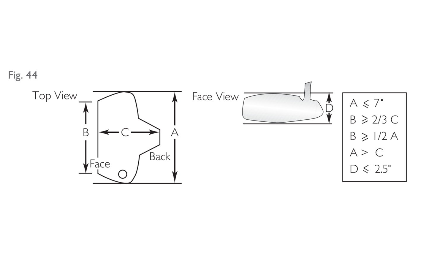 For traditionally shaped heads, these dimensions will be measured on horizontal lines between vertical projections of the outermost points of:
• the heel and the toe of the head;
• the heel and the toe of the face; and
• the face and the back;
and on vertical lines between the horizontal projections of the outermost points of the sole and the top of the head.
For unusually shaped heads, the toe to heel dimension may be made at the face.
Given all of the dimensional restrictions for putter heads, which help define the size and shape, the additional clause regarding unusually shaped heads is rarely, if ever, applied.
It is important to note that appendages are not permitted if their only purpose is to make the clubhead meet the dimensional specifications described in this provision (see Section 4a(iv) and Figure 29).
For traditionally shaped heads, these dimensions will be measured on horizontal lines between vertical projections of the outermost points of:
• the heel and the toe of the head;
• the heel and the toe of the face; and
• the face and the back;
and on vertical lines between the horizontal projections of the outermost points of the sole and the top of the head.
For unusually shaped heads, the toe to heel dimension may be made at the face.
Given all of the dimensional restrictions for putter heads, which help define the size and shape, the additional clause regarding unusually shaped heads is rarely, if ever, applied.
It is important to note that appendages are not permitted if their only purpose is to make the clubhead meet the dimensional specifications described in this provision (see Section 4a(iv) and Figure 29).
Fig 42: Head dimensions (woods)
Fig 43: Volume measurement
Electronic scales (set to zero) with water-filled container and club head ready for submergence.
Fig 44: Head dimensions (putters)
2.4c
Spring Effect and Dynamic Properties
The design, material and/or construction of, or any treatment to, the clubhead (which includes the club face) must not:
(i) have the effect of a spring which exceeds the limit set forth in the Pendulum Test Protocol on file with The R&A and USGA; or
(ii) incorporate features or technology including, but not limited to, separate springs or spring features, that have the intent of, or the effect of, unduly influencing the clubhead’s spring effect; or
(iii) unduly influence the movement of the ball.
Note: (i) above does not apply to putters.
Given that the “spring-effect rule” is purely a performance related limit which cannot be measured easily in the field without specialized equipment and cannot be assessed through a visual inspection of the clubhead, The R&A and USGA have compiled and maintain a List of Conforming Driver Heads. This List can be accessed via The R&A’s or USGA’s website and it is updated weekly.
For competitions involving highly skilled players, a Model Local Rule may be introduced requiring players to use a driver which is included on this List. This Local Rule is an additional requirement for these players, which means that, not only must their clubs conform to the Equipment Rules, but the model and loft must also be included on the List of Conforming Driver Heads. This Local Rule is not recommended for use at other levels of golf. However, it is the player’s responsibility to ensure that his or her driver conforms to the Equipment Rules if it is not on the List.
As well as meeting the requirements of clause (i) in the above Rule, clubs are also tested for compliance to clause (ii) using the Pendulum at points on the face other than at the centre and, depending on the results, other tests may be carried out. Any club which is found to include a feature that is designed to act like a spring, independent of the level of flexibility achieved by the design, could be ruled non-conforming.
Finally, if claims of “spring like” qualities are made by the manufacturer which suggest that a club is manufactured to be in excess of the limit, or there is evidence to suggest that the club is indeed over the limit, then the club would be deemed to be non-conforming.
2.4d
Striking Faces
The clubhead must have only one striking face, except that a putter may have two such faces if their characteristics are the same, and they are opposite each other.
The exception for putters was introduced in order to accommodate traditional blade-type putters.
Determining whether a surface constitutes a second (or third) striking face is often a matter of interpretation. However, in general, a surface should be considered an additional striking face if:
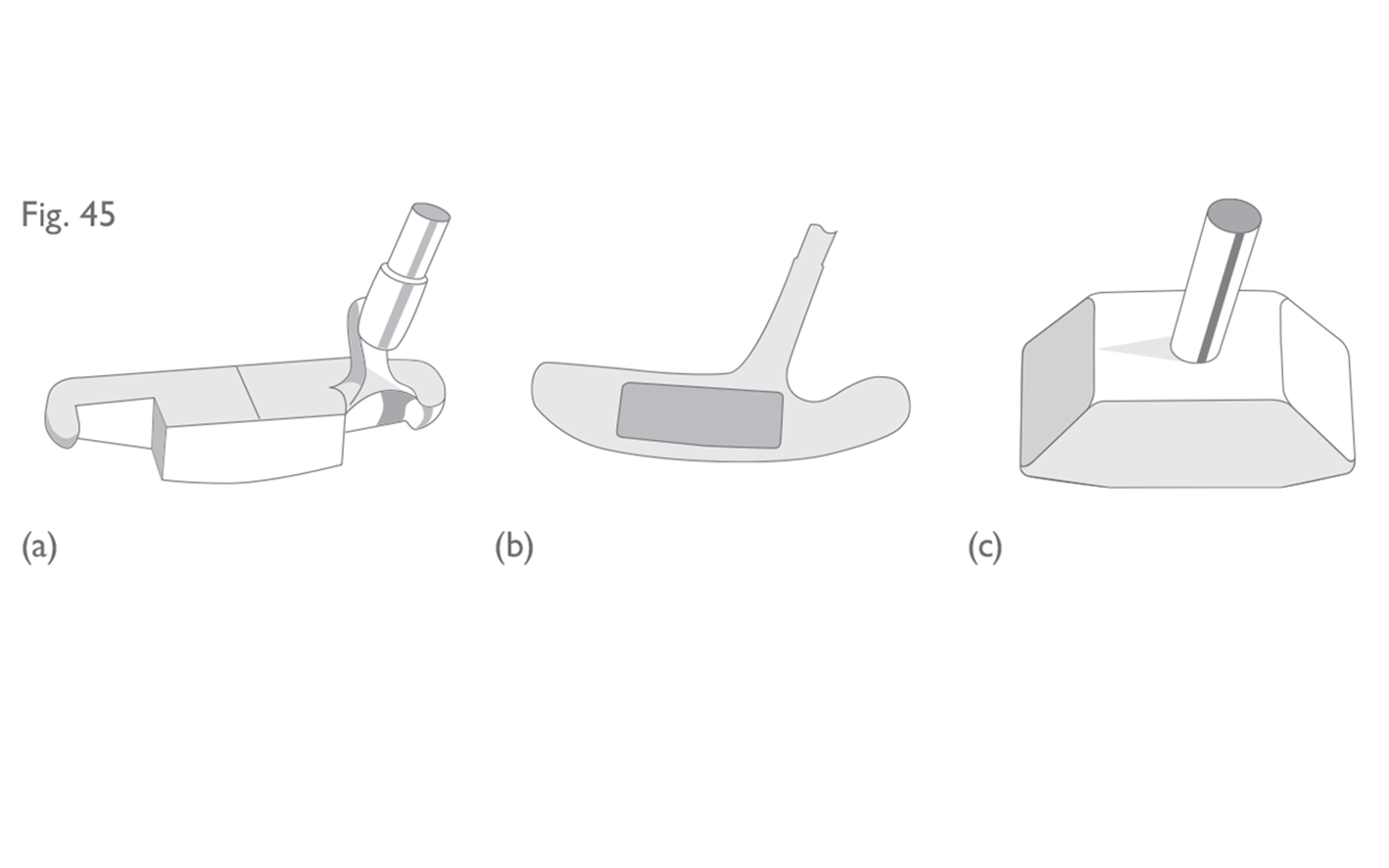 The addition of lead tape to the secondary face of a dual-faced putter would not be contrary to the Equipment Rules. In addition, cosmetic or decorative markings on one of two permissible surfaces, that do not affect the performance, will not usually create a different striking face in breach of this provision.
- the area is flat and it is clearly designed to be used for striking the ball; or
- it is opposite the intended face and consists of a flat surface of a different loft and/or material; or
- it is a flat surface on the toe and/or heel of a cylindrical, rectangular or square head design which could effectively be used to strike the ball; or
- it could otherwise effectively be used to strike the ball.
Fig 45 a b c: Striking faces - examples of non-conforming putters
(a) This putter has one small face at the front and a second much longer face at the back. (b) This putter has a 'balata' type inset in the front, but the back of the head is a smooth, flat metal surface. (c) This putter has two identical surfaces at the front and the back. However, it also has a third striking face at the toe.
2.5
Club Face
2.5a
General
The face of the club must be hard and rigid and must not impart significantly more or less spin to the ball than a standard steel face (some exceptions may be made for putters). Except for such markings listed below, the club face must be smooth and must not have any degree of concavity.
If claims of excessive spin are made by the manufacturer, or if there is strong supporting evidence of excessive spin, then the club would be deemed to be non-conforming.
The “hardness” provision is particularly relevant to putters, many of which have a urethane or other “soft” material inset in the face.
The measure for hardness is made using a durometer. A putter face must be no less than 85 on a Shore A scale durometer. A simple measure of hardness in the field would be to use a fingernail. If a fingernail leaves a significant imprint in the face of a club, it is possible that the material does not satisfy the “hard and rigid” requirement. The face of a wood or iron club must be substantially harder than a putter face, i.e. no less than 75 on the Shore D scale.
In the field, “rigidity” is interpreted to mean that the face should not have any visible signs of movement or flex when manual pressure is exerted.
Where there is an inset in the face of the club, it should be flush with the rest of the face so that the face can still be considered smooth with no concavity. While we interpret concavity in this provision strictly, we also recognize that, due to manufacturing tolerances, it is sometimes difficult for every insert to be exactly flush with the rest of the face. As a result, we allow an inset to be up to 0.006 inches (0.15 mm) proud of the rest of the face or no deeper than 0.004 inches (0.1 mm) below the rest of the face.
2.5b
Impact Area Roughness and Material
Except for markings specified in the following paragraphs, the surface roughness within the area where impact is intended (the “impact area”) must not exceed that of decorative sandblasting, or of fine milling (see Fig. 46).
The whole of the impact area must be of the same material (exceptions may be made for clubheads made of wood).
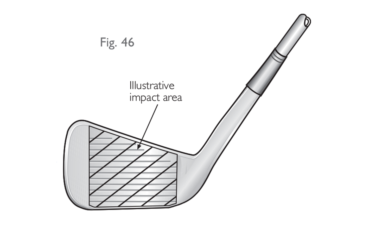 (i) Definition of “Impact Area”
Irons
For iron clubs, the “impact area” is deemed to be that part of the club face where a treatment has been applied (for instance grooves, sandblasting, etc.) or the central strip down the middle of the club face having a width of 1.68 inches (42.67 mm), whichever is greater.
Woods
The impact area on driving clubs and fairway woods is deemed to be the central strip down the middle of the clubface having a width of 1.68 inches (42.67 mm) – see Figure 47a.
(i) Definition of “Impact Area”
Irons
For iron clubs, the “impact area” is deemed to be that part of the club face where a treatment has been applied (for instance grooves, sandblasting, etc.) or the central strip down the middle of the club face having a width of 1.68 inches (42.67 mm), whichever is greater.
Woods
The impact area on driving clubs and fairway woods is deemed to be the central strip down the middle of the clubface having a width of 1.68 inches (42.67 mm) – see Figure 47a.
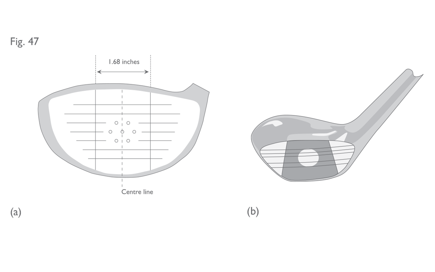 NOTE: Grooves and/or punch marks indicating a traditional impact area (see Figure 47b), or any groove which encroaches into the heel or toe portions of the impact area by less than 0.25 inches (6.35 mm), will not be considered to be within the impact area. However, any such markings must not be designed to unduly influence, or have the effect of unduly influencing, the movement of the ball.
For clubs with insets in the face, the boundary of the impact area is defined by the boundary of the inset, as long as any markings outside the boundary do not encroach the impact area by more than 0.25 inches (6.35 mm) and/or are not designed to influence the movement of the ball.
Moreover, the inset itself must extend to at least 0.84 inches (21.34 mm) either side of the centre line of the face and to within at least 0.2 inches (5.08 mm) of the top line and leading edge of the face.
IMPORTANT NOTE:
The above definitions of the impact area only apply to models of clubs manufactured on or after 1 January 2010. For clubs manufactured prior to 1 January 2010, please refer to the end of Supplementary Paper B.
(ii) Impact Area Roughness
When dealing with the surface roughness of a club face (not including putters, see Section 5f), the claims made by the manufacturer must be taken into account – especially if there is a claim that the roughness of the face influences the movement of the ball. In the absence of such claims, the ruling is made purely on the amount of roughness there is. Sandblasting or other treatments of roughness greater than 180 micro inches (4.5 µmetre) are not permitted. In addition to this requirement for roughness, milling is not permitted if the crest to trough depth exceeds 0.001 inches (0.025 mm). A reasonable tolerance is allowed for both of the above measurements. Non-conforming sandblasting or milling usually feels rough to the touch.
(iii) Impact Area Material
The requirement that the whole of the impact area must be of the same material does not apply to clubs made of wood or putters (see Section 5f). The reason why it does not apply to wooden headed clubs is to allow the continued use of traditional wooden clubs which have plastic insets and brass screws in the centre of the face. This design was commonly used in the old persimmon woods, some of which may still be in use. It is worth noting that a club face or inset made of a composite material would be considered to be of a single material and, therefore, would not be contrary to this provision.
Metal wood club faces which have insets of different material not trapezoidal in shape may be permitted if the height of the inset meets the definition of the impact area and the width of the inset is the same as the height in at least one point. However, in order to preserve the intent of the “same material” Rule, clubs which have unusually shaped insets of different material (i.e. other than circular, oval, square or rectangular) would not normally be permitted.
If an inset of different material is permitted under the above guideline, the inset would be considered the impact area for that club. Therefore, any markings outside that area need not conform to the specifications in Section 5c. However, such markings must not be designed to unduly influence the movement of the ball.
NOTE: Grooves and/or punch marks indicating a traditional impact area (see Figure 47b), or any groove which encroaches into the heel or toe portions of the impact area by less than 0.25 inches (6.35 mm), will not be considered to be within the impact area. However, any such markings must not be designed to unduly influence, or have the effect of unduly influencing, the movement of the ball.
For clubs with insets in the face, the boundary of the impact area is defined by the boundary of the inset, as long as any markings outside the boundary do not encroach the impact area by more than 0.25 inches (6.35 mm) and/or are not designed to influence the movement of the ball.
Moreover, the inset itself must extend to at least 0.84 inches (21.34 mm) either side of the centre line of the face and to within at least 0.2 inches (5.08 mm) of the top line and leading edge of the face.
IMPORTANT NOTE:
The above definitions of the impact area only apply to models of clubs manufactured on or after 1 January 2010. For clubs manufactured prior to 1 January 2010, please refer to the end of Supplementary Paper B.
(ii) Impact Area Roughness
When dealing with the surface roughness of a club face (not including putters, see Section 5f), the claims made by the manufacturer must be taken into account – especially if there is a claim that the roughness of the face influences the movement of the ball. In the absence of such claims, the ruling is made purely on the amount of roughness there is. Sandblasting or other treatments of roughness greater than 180 micro inches (4.5 µmetre) are not permitted. In addition to this requirement for roughness, milling is not permitted if the crest to trough depth exceeds 0.001 inches (0.025 mm). A reasonable tolerance is allowed for both of the above measurements. Non-conforming sandblasting or milling usually feels rough to the touch.
(iii) Impact Area Material
The requirement that the whole of the impact area must be of the same material does not apply to clubs made of wood or putters (see Section 5f). The reason why it does not apply to wooden headed clubs is to allow the continued use of traditional wooden clubs which have plastic insets and brass screws in the centre of the face. This design was commonly used in the old persimmon woods, some of which may still be in use. It is worth noting that a club face or inset made of a composite material would be considered to be of a single material and, therefore, would not be contrary to this provision.
Metal wood club faces which have insets of different material not trapezoidal in shape may be permitted if the height of the inset meets the definition of the impact area and the width of the inset is the same as the height in at least one point. However, in order to preserve the intent of the “same material” Rule, clubs which have unusually shaped insets of different material (i.e. other than circular, oval, square or rectangular) would not normally be permitted.
If an inset of different material is permitted under the above guideline, the inset would be considered the impact area for that club. Therefore, any markings outside that area need not conform to the specifications in Section 5c. However, such markings must not be designed to unduly influence the movement of the ball.
Fig 46: Iron impact area
Fig 47: Impact area for driving clubs and fairway woods
(a) Metal wood head showing size and shape of impact area. (b) Grooves indicating traditional impact area.
2.5c
Impact Area Markings
If a club has grooves and/or punch marks in the impact area they must meet the following specifications:
(i) Grooves
• Grooves must be straight and parallel.
• Grooves must have a symmetrical cross-section and have sides which do not converge (see Fig. 48).
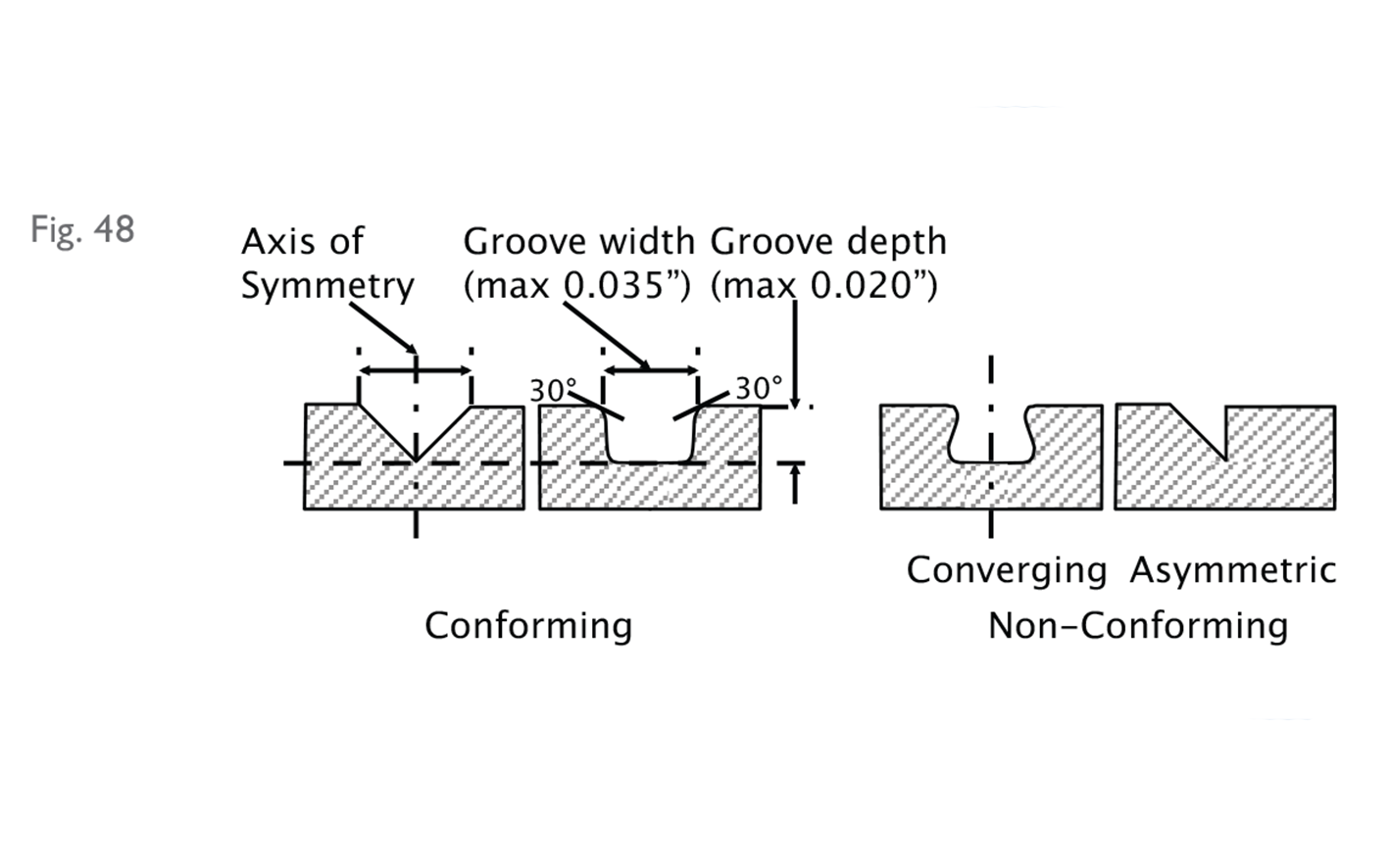 • *For clubs that have a loft angle greater than or equal to 25 degrees, grooves must have a plain cross-section.
• The width, spacing and cross-section of the grooves must be consistent throughout the impact area (some exceptions may be made for woods).
• The width (W) of each groove must not exceed 0.035 inches (0.9 mm), using the 30 degree method of measurement on file with The R&A and USGA.
• The distance between edges of adjacent grooves (S) must not be less than three times the width of the grooves, and not less than 0.075 inches (1.905 mm).
• The depth of each groove must not exceed 0.020 inches (0.508 mm).
• *For clubs other than driving clubs, the cross-sectional area (A) of a groove divided by the groove pitch (W+S) must not exceed 0.0030 square inches per inch (0.0762 mm2/mm) (see Fig. 49).
• *For clubs that have a loft angle greater than or equal to 25 degrees, grooves must have a plain cross-section.
• The width, spacing and cross-section of the grooves must be consistent throughout the impact area (some exceptions may be made for woods).
• The width (W) of each groove must not exceed 0.035 inches (0.9 mm), using the 30 degree method of measurement on file with The R&A and USGA.
• The distance between edges of adjacent grooves (S) must not be less than three times the width of the grooves, and not less than 0.075 inches (1.905 mm).
• The depth of each groove must not exceed 0.020 inches (0.508 mm).
• *For clubs other than driving clubs, the cross-sectional area (A) of a groove divided by the groove pitch (W+S) must not exceed 0.0030 square inches per inch (0.0762 mm2/mm) (see Fig. 49).
 • Grooves must not have sharp edges or raised lips.
• *For clubs that have a loft angle greater than or equal to 25 degrees, groove edges must be substantially in the form of a round having an effective radius which is not less than 0.010 inches (0.254 mm) when measured as shown in Fig. 50, and not greater than 0.020 inches (0.508 mm). Deviations in effective radius within 0.001 inches (0.0254 mm) are permissible.
• Grooves must not have sharp edges or raised lips.
• *For clubs that have a loft angle greater than or equal to 25 degrees, groove edges must be substantially in the form of a round having an effective radius which is not less than 0.010 inches (0.254 mm) when measured as shown in Fig. 50, and not greater than 0.020 inches (0.508 mm). Deviations in effective radius within 0.001 inches (0.0254 mm) are permissible.
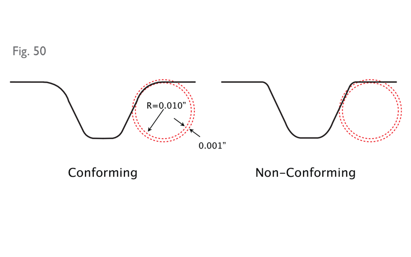 (ii) Punch Marks
• The maximum dimension of any punch mark must not exceed 0.075 inches (1.905 mm).
(ii) Punch Marks
• The maximum dimension of any punch mark must not exceed 0.075 inches (1.905 mm).
• The distance between adjacent punch marks (or between punch marks and grooves) must not be less than 0.168 inches (4.27 mm), measured from centre to centre.
• The depth of any punch mark must not exceed 0.040 inches (1.02 mm).
• Punch marks must not have sharp edges or raised lips.
• *For clubs that have a loft angle greater than or equal to 25 degrees, punch mark edges must be substantially in the form of a round having an effective radius which is not less than 0.010 inches (0.254 mm) when measured as shown in Figure 50, and not greater than 0.020 inches (0.508 mm). Deviations in effective radius within 0.001 inches (0.0254 mm) are permissible.
Note 1: The groove and punch mark specifications above indicated by an asterisk (*) apply only to new models of clubs manufactured on or after 1 January 2010 and any club where the face markings have been purposely altered, for example, by re-grooving. For further information on the status of clubs available before 1 January 2010, refer to the ‘‘Equipment Search’’ section of www.randa.org or “Club and Ball Lists” section of www.usga.org.
Note 2: The Committee may require, in the Model Local Rule, that the clubs the player carries must conform to the groove and punch mark specifications above indicated by an asterisk (*). This Term is recommended only for competitions involving expert players. For further information, refer to to the Commitee Procedures, Section 8, Model Local Rule G-2 in The Official Guide to the Rules of Golf. The groove and punch mark specifications were updated in 2010 and many pre-2010 models of clubs do not meet the new specifications. The above Notes mean that the vast majority of golfers can continue to carry clubs manufactured prior to 2010 until at least 2024. Supplementary Paper B sets out guidance on how to measure width, depth and separation of grooves using the ‘ink and scratch’ method and how to determine the conformance status of a club to the pre-2010 Equipment Rules. This is an adequate method for use in the field where the Committee has not introduced the Groove and Punch Mark Model Local Rule (i.e. at the non-elite level). There are several methods which can be used to measure grooves and punch marks against the updated specifications detailed above – most of which require specialized equipment. Full details of the procedure for measuring club face markings and determining their status against the post-2010 specifications can be found on The R&A’s and USGA’s websites. A summary can also be found in Supplementary Paper C. As noted, The R&A and USGA do not recommend adoption of the Model Local Rule referenced in Note 2 unless the competition involves professional-level players and/or players at the highest levels of amateur golf. In order to assist players and officials to determine whether a player’s clubs meet the condition, The R&A and USGA have compiled an informational database of irons, wedges, fairway woods and hybrids that have been submitted to either organization and evaluated for conformance to the updated specifications. This information is available on The R&A’s and USGA’s websites, respectively. Notably, clubs where the face markings have been purposely altered, for example, by re-grooving must conform to the 2010 groove and punch mark specifications. However, clubs which have only been refurbished back to their original state (perhaps by light sandblasting) may still benefit from the period of grace given to pre-2010 models. For the avoidance of doubt, all new models available after 31 December 2009 must conform to the current Equipment Rules. (iii) Groove/Punch Mark Combinations If punch marks are used in conjunction with grooves, the following guidelines apply: Iron Clubs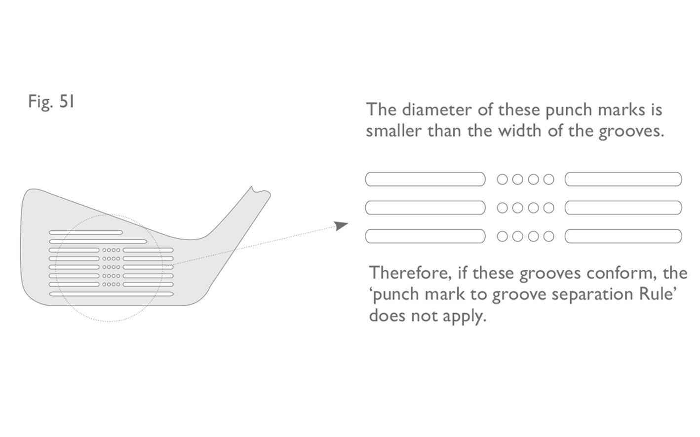
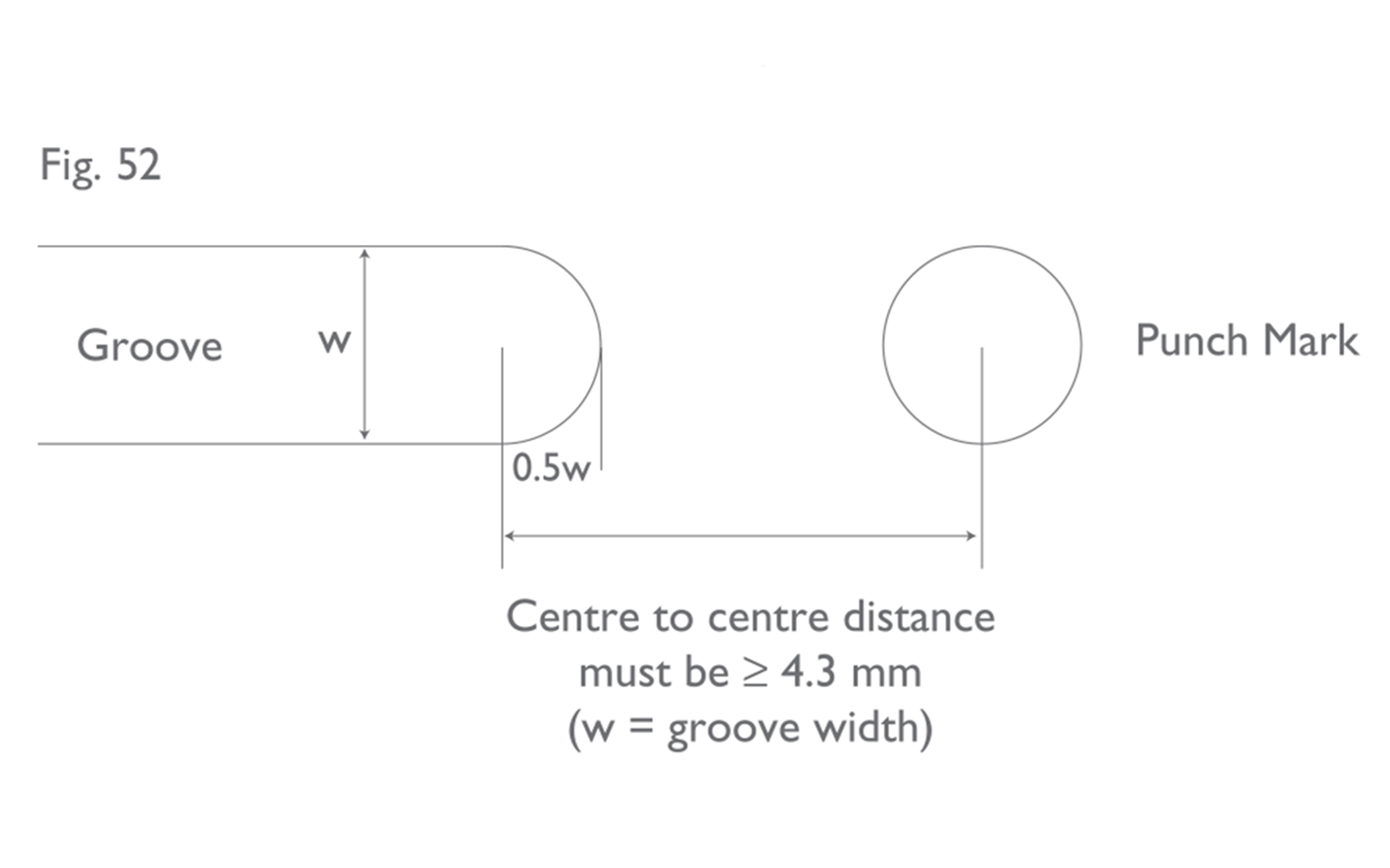
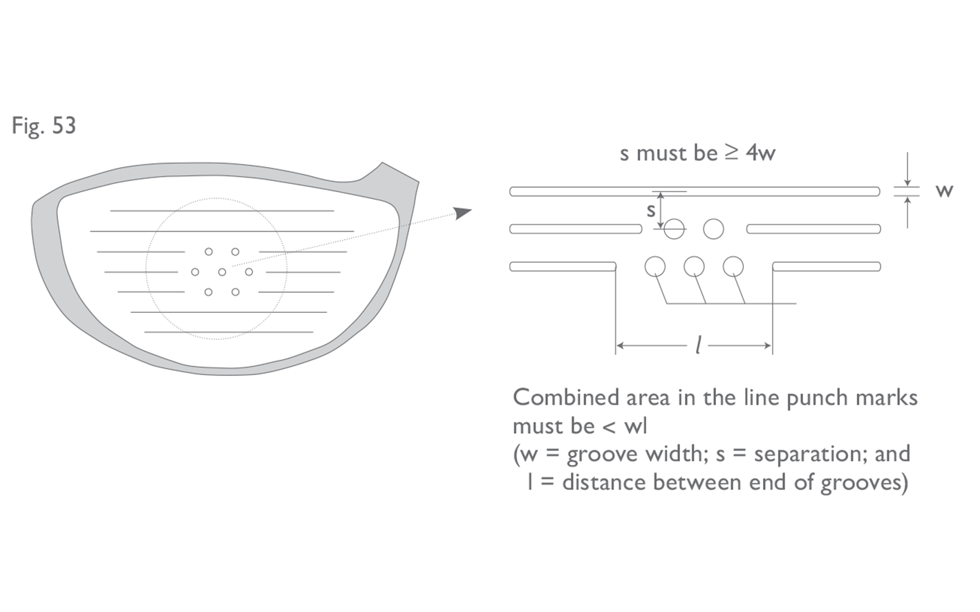
Fig 48: Groove cross-section
Fig 49: Groove area/pitch
Fig 50: Groove edge sharpness
• The distance between adjacent punch marks (or between punch marks and grooves) must not be less than 0.168 inches (4.27 mm), measured from centre to centre.
• The depth of any punch mark must not exceed 0.040 inches (1.02 mm).
• Punch marks must not have sharp edges or raised lips.
• *For clubs that have a loft angle greater than or equal to 25 degrees, punch mark edges must be substantially in the form of a round having an effective radius which is not less than 0.010 inches (0.254 mm) when measured as shown in Figure 50, and not greater than 0.020 inches (0.508 mm). Deviations in effective radius within 0.001 inches (0.0254 mm) are permissible.
Note 1: The groove and punch mark specifications above indicated by an asterisk (*) apply only to new models of clubs manufactured on or after 1 January 2010 and any club where the face markings have been purposely altered, for example, by re-grooving. For further information on the status of clubs available before 1 January 2010, refer to the ‘‘Equipment Search’’ section of www.randa.org or “Club and Ball Lists” section of www.usga.org.
Note 2: The Committee may require, in the Model Local Rule, that the clubs the player carries must conform to the groove and punch mark specifications above indicated by an asterisk (*). This Term is recommended only for competitions involving expert players. For further information, refer to to the Commitee Procedures, Section 8, Model Local Rule G-2 in The Official Guide to the Rules of Golf. The groove and punch mark specifications were updated in 2010 and many pre-2010 models of clubs do not meet the new specifications. The above Notes mean that the vast majority of golfers can continue to carry clubs manufactured prior to 2010 until at least 2024. Supplementary Paper B sets out guidance on how to measure width, depth and separation of grooves using the ‘ink and scratch’ method and how to determine the conformance status of a club to the pre-2010 Equipment Rules. This is an adequate method for use in the field where the Committee has not introduced the Groove and Punch Mark Model Local Rule (i.e. at the non-elite level). There are several methods which can be used to measure grooves and punch marks against the updated specifications detailed above – most of which require specialized equipment. Full details of the procedure for measuring club face markings and determining their status against the post-2010 specifications can be found on The R&A’s and USGA’s websites. A summary can also be found in Supplementary Paper C. As noted, The R&A and USGA do not recommend adoption of the Model Local Rule referenced in Note 2 unless the competition involves professional-level players and/or players at the highest levels of amateur golf. In order to assist players and officials to determine whether a player’s clubs meet the condition, The R&A and USGA have compiled an informational database of irons, wedges, fairway woods and hybrids that have been submitted to either organization and evaluated for conformance to the updated specifications. This information is available on The R&A’s and USGA’s websites, respectively. Notably, clubs where the face markings have been purposely altered, for example, by re-grooving must conform to the 2010 groove and punch mark specifications. However, clubs which have only been refurbished back to their original state (perhaps by light sandblasting) may still benefit from the period of grace given to pre-2010 models. For the avoidance of doubt, all new models available after 31 December 2009 must conform to the current Equipment Rules. (iii) Groove/Punch Mark Combinations If punch marks are used in conjunction with grooves, the following guidelines apply: Iron Clubs
- Small punch marks which are in line with a conforming groove, and which would be totally contained within a continuation of the groove do not have to meet the punch mark to groove specifications (See Figure 51). However, if the diameter of such punch marks exceeds the width of the groove, then they must meet the specifications.
Fig 51: Groove and punch mark combination
Fig 52: Spacing of punch marks with in-line grooves
- When measuring the centre to centre distance between a punch mark and the end of an in-line groove, the centre of the groove is deemed to be half a groove width from the end edge of the groove (See Figure 52).
- there must be no more than three in-line punch marks in the part of the groove that is missing (i.e. in the gap between the ends of the partial grooves);
- the combined area of all of the in-line punch marks in any one such gap must not exceed the area of the missing groove; and
- the separation of the in-line punch marks from adjacent parallel grooves – measured from centre to centre – must be at least four times the width of the groove.
Fig 53: Exceptions for metal woods
2.5d
Decorative Markings
The centre of the impact area may be indicated by a design within the boundary of a square whose sides are 0.375 inches (9.53 mm) in length. Such a design must not unduly influence the movement of the ball. Decorative markings are permitted outside the impact area.
This provision permits small, decorative logos in the centre of the face or at the side of the impact area (see Fig. 54). Decorative markings or logos that marginally encroach on the impact area, i.e. by less than 0.25 inches (6.35 mm), may be permitted. However, any such markings must not be designed to unduly influence or have the effect of unduly influencing the movement of the ball. Markings outside the impact area which are designed to influence the movement of the ball when it has been mis-hit would be contrary to this provision.
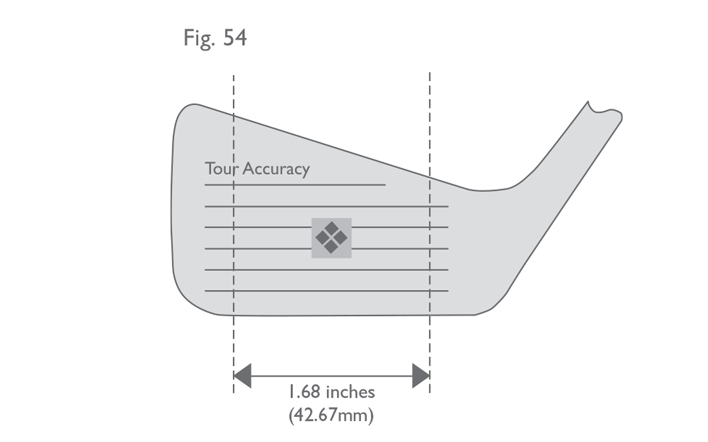
Fig 54: Decorative markings
The decorative marking in the centre fits into the boundaries of a square whose sides are 0.375" (9.52 mm) in length, and thus conforms with the Rules. However, the word "Accuracy" is deemed to significantly encroach on the impact area, and therefore the club is non-conforming.
2.5e
Non-metallic Club Face Markings
The above specifications do not apply to clubheads made of wood on which the impact area of the face is of a material of hardness less than the hardness of metal and whose loft angle is 24 degrees or less, but markings which could unduly influence the movement of the ball are prohibited.
2.5f
Putter Face
Any markings on the face of a putter must not have sharp edges or raised lips. The specifications with regard to roughness, material and markings in the impact area do not apply.
In addition, if a groove or the grooves on the face of a putter exceed 0.035 inches (0.9 mm) in width and 0.020 inches (0.508 mm) in depth, the following guidelines apply:
- The width may not exceed 0.060 inches (1.524 mm);
- The width to spacing ratio must be no less than 1:1; and
- The depth must be less than the width, and may not exceed 0.040 inches (1.016 mm).